17
V700-L21
User's Manual
Section 2
2.1 CIDRW controller: Model V700-L21
Section 2
Unit Specifications
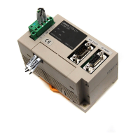
2.1.3 Dimensional drawing and mounting method
● Mounting method
Install the controller using the four mounting holes and four M4 screws together with the enclosed
washers.
* Be sure to limit the tightening torque for the M4 screws to 1.2 N-m or less.
* Do not apply an organic solvent such as thread glue to the threads.
Case material Steel sheet (SPCC-P) (Unit: mm)
indicator
POWER
indicators
STATUS
Mounting holes (1: 2)
130 0.2
4-M4
(mounting holes)
4- 4.5
28
P6 3
30
150
130
7
3
24
151
167
151 0.2

 Loading...