38
Section 3
3.1 Connection work and startup
V700-L21
User's Manual
Section 3
System Connections
3.1 Connection work and startup
➀
Connect the CIDRW controller to an upstream controller (equipment controller, etc.) with an RS-
232C cable. The maximum allowable cable length is limited to 15 m. According to the intended
CIDRW system configuration, choose the protocol parameters for the CIDRW controller and Baud
rate for communications with the link unit. Parameter setting can be achieved in setup mode.
➁
Connect the CIDRW controller to the link unit with an RS-232C cable. The maximum allowable
cable length is limited to 15 m. Determine the DIP-SW setting so that the Baud rate for the link unit
is same as that for the CIDRW controller.
➂
Connect the IDRW head to the link unit. (A pair of mutually connected IDRW head and link unit is
simply called "head".) The IDRW head is powered by the link unit. If the cable needs to be
extended, use a straight cable as an extension cable. The maximum allowable cable length is 4 m
(maximum 3 m for an extension cable).
➃
In a multi-head application, connect the heads in multidrop arrangement per RS-485. The maximum
allowable total cable length is 50 m.
➄
Using the setup DIP-SW on the link unit, define the node Nos. and enable/disable the terminators.
Each node, up to the highest number of node, is assigned with a unique ID No. beginning with 1.
Set the terminator setting to ON for the link units on both ends of multidrop, and to OFF for other
units. In the case of single-head configuration, set the terminator setting for the link unit in question
to OFF.
➅
When the CIDRW system is power UP with its equipment connected, the CIDRW controller checks
the system by detecting the status of the connected heads, then the CIDRW system becomes
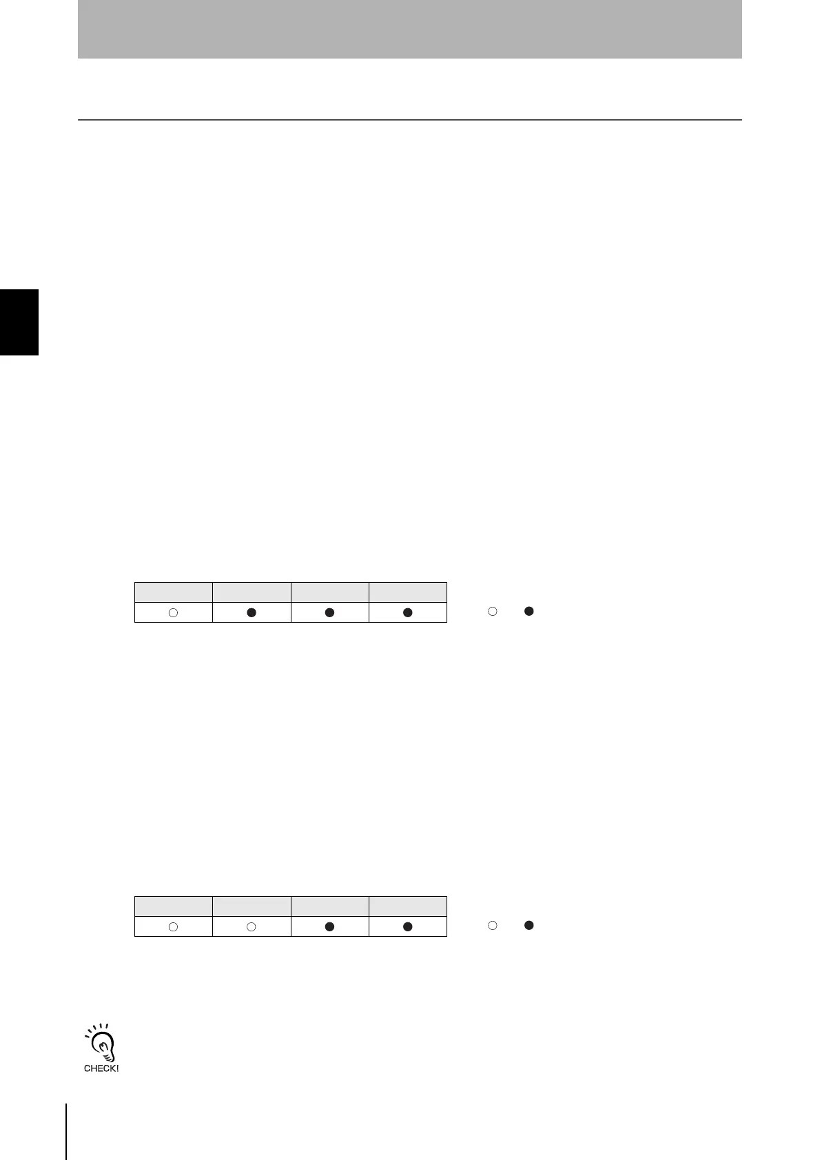
ready for service. Once the CIDRW is started without problems, the status indicators on the CIDRW
controller will appear as follows:
<Detection of heads>
The following two schemes are possible for automatic recognition of heads. Either scheme can be cho-
sen in the setup mode. The factory-setting is "auto count".
➀
Auto count:A number of detected heads is taken as "number of heads".
Regardless of the variation in currently connected heads, the number of heads is auto-
matically recognized.
➁
Specified number of heads:A number of detected heads (1 to 31) is compared with a specified
number.
By this choice, it is possible to detect a fault (ALARMS) if the number of
active heads varies owing to, for example, failed heads.
If a particular head is disconnected or a fault is detected with a connected head, and, as a result, a
number of detected heads does not match a specified number, an alarm is triggered.
OPERATING ALARMS BUSY ERROR
: Lit, : Unlit
OPERATIONG ALARMS BUSY ERROR
: Lit, : Unlit
When attempting to change the mode switch setting on CIDRW controller or set up the DIP-SW on
link unit, or connect a cable, turn OFF the power supply to the CIDRW system. Next, make fully sure
that the intended settings and connections are correct, and only then, power ON the system again.

 Loading...


