6 Programming Features
127
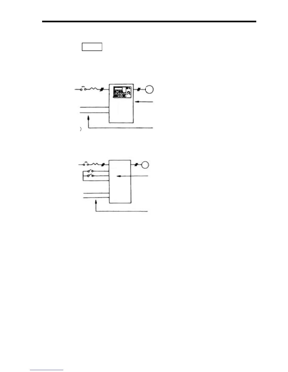
Current Reference Selection
After changing the DIP switch (V-I switch of SW2) to the “I” side,
press on the Digital Operator, then set the following constants.
Current reference (4 to 20 mA): constant n004 = 3
Current reference (0 to 20 mA): constant n004 = 4
• Setting: n003 = 0
• Setting: n003 = 1
Frequency reference gain (n060)/bias (n061) can be set even when cur-
rent reference input is selected. For details, refer to Adjusting Speed
Setting Signal on page 76.
Press the Digital Operator keys to run
or stop the Inverter. Switch FWD and
REV run by setting the F/R LED.
Set the frequency by the analog cur-
rent signal [0 % to 100 % (max. fre-
quency)/4 to 20 mA or 0 to 20 mA]
connected to the control circuit termi-
nals.
Switch run/stop and FWD/REV run
with switching device connected to the
control circuit terminal.
Multi-function input terminals S1 and
S2 are set to Forward run/stop
(n050=1) and Reverse run/stop
(n051=2) respectively.
Set frequency by the analog current
signal [0 % to 100 % (max. frequen-
cy)/4 to 20 mA or 0 to 20 mA] con-
nected to the control circuit terminal.
PRGM
FS
FR
FC
IM
Current
Reference
4 to 20 mA
or
0 to 20 mA
(n004 = 3 or 4
S1
S2
SC
FS
FR
FC
IM
Current
Reference
4 to 20 mA
or
0 to 20 mA
(n004 = 3 or 4)
FWD Run/Stop
REV Run/Stop