140
• When n141 is set to 1 or higher:
n004 (Frequency Reference Selection) cannot be set to 2, 3, or 4 (fre-
quency reference of 0 to 10 V, 4 to 20 mA, or 0 to 20 mA, respec-
tively).
When n128 (PID Control Selection) is set to a value other than 0
(with PID control), n164 (PID Feedback Value Selection) cannot be
set to 0, 1, or 2 (feedback values of 0 to 10 V, 4 to 20 mA, or 0 to
20 mA, respectively).
• Constant n141 cannot be set to 1 when n004 is set to 2, 3, or 4, and
n128 is set to 1 and n164 is set to 0,1, or 2.
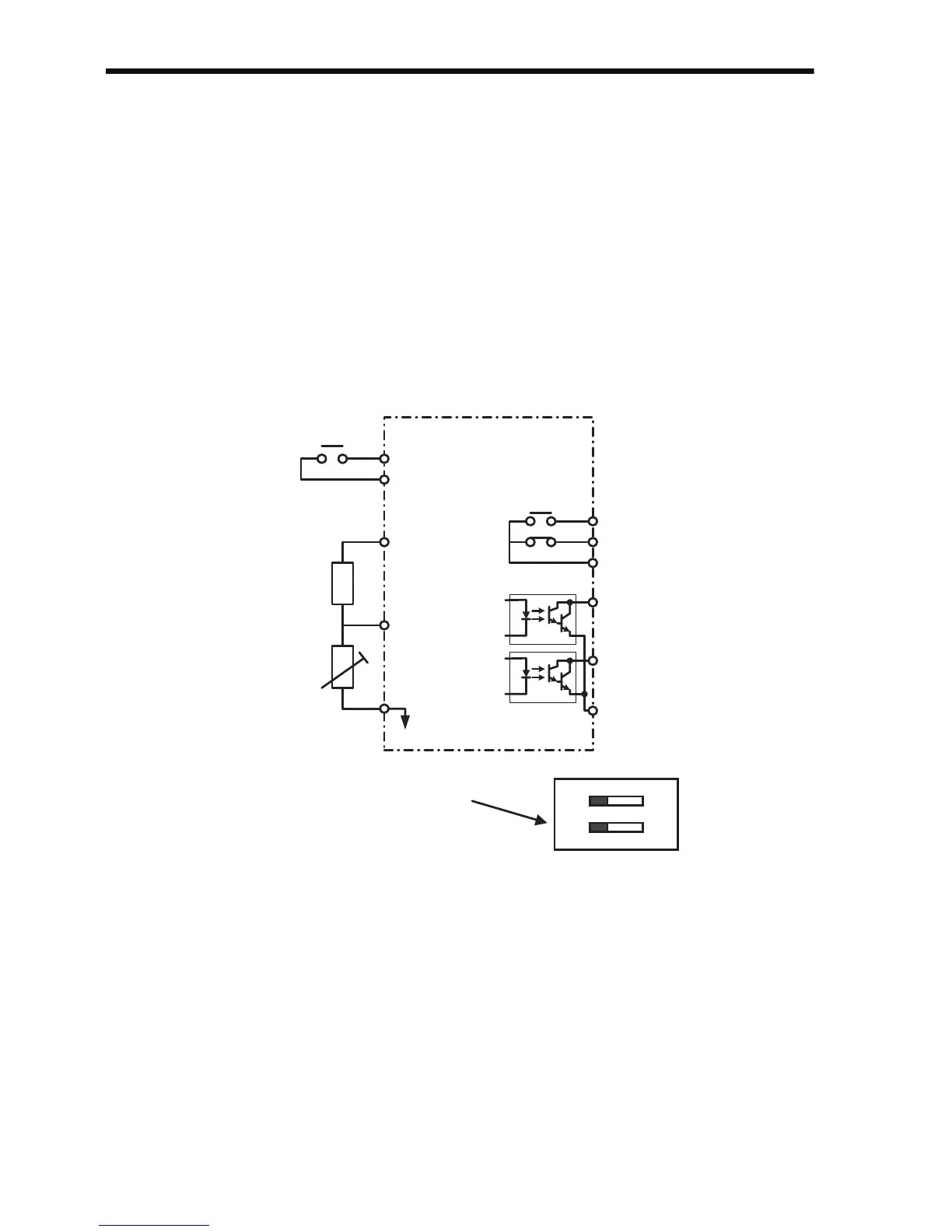
Terminal Connection Diagram of PTC Thermistor Input Motor Over-
heat Protection
+V (+12 V)
FR
(0 to 10 V:
20 kΩ)
FC
MA
MB
MC
P1
P2
PC
SW2
OFF
V
ON
I
Multi-function
input
Voltage divider,
18 kΩ
PTC thermistor
Multi-function
output
Multi-function
output PHC
Note: When performing motor overheat
protection using the PTC
thermistor input, be sure to set the
V-I switch (SW2) on the DIP switch
on the control circuit board to V.