2.3 Detailed Description of the Services
21
■ Write Variable Area
This service writes data to a variable area.
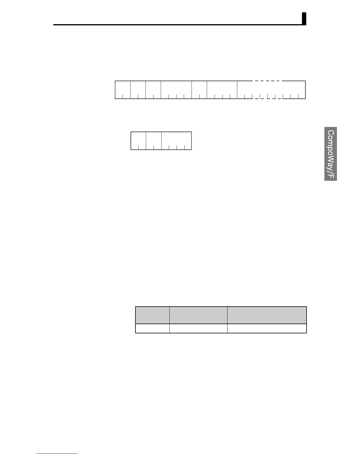
Service Request PDU
Note: The write data 12 indicates the weekly timer.
Service Response PDU
● Variable Type and Write Start Address
For details on variable types and write start addresses, see 3.1 Variable
Area (Data Range) List.
Variable type C0 is read-only.
● Bit Position
Bits positions are always 00 except for work bits and HR bits. With the
ZEN, bit access supported only for work bits and HR bits.
For details on bits and applications methods, refer to 1-4 Memory Areas
in the ZEN Programmable Relay Operation Manual.
Note: Refer to Reading Work Bits and HR Bits on page 20 for details
on reading work bits and HR bits.
● Number of Elements
Always to 0001.
● Response Code
Normal Completion
MRC SRC
0
222 4 2 4
102 0100
Variable
type
Start
write address
Bit
position
Number of
elements
Write Data
(for number of elements)
8 or 12

 Loading...


