Oneida Air Systems, Inc.18
Assembly Instructions (Continued)
Wall
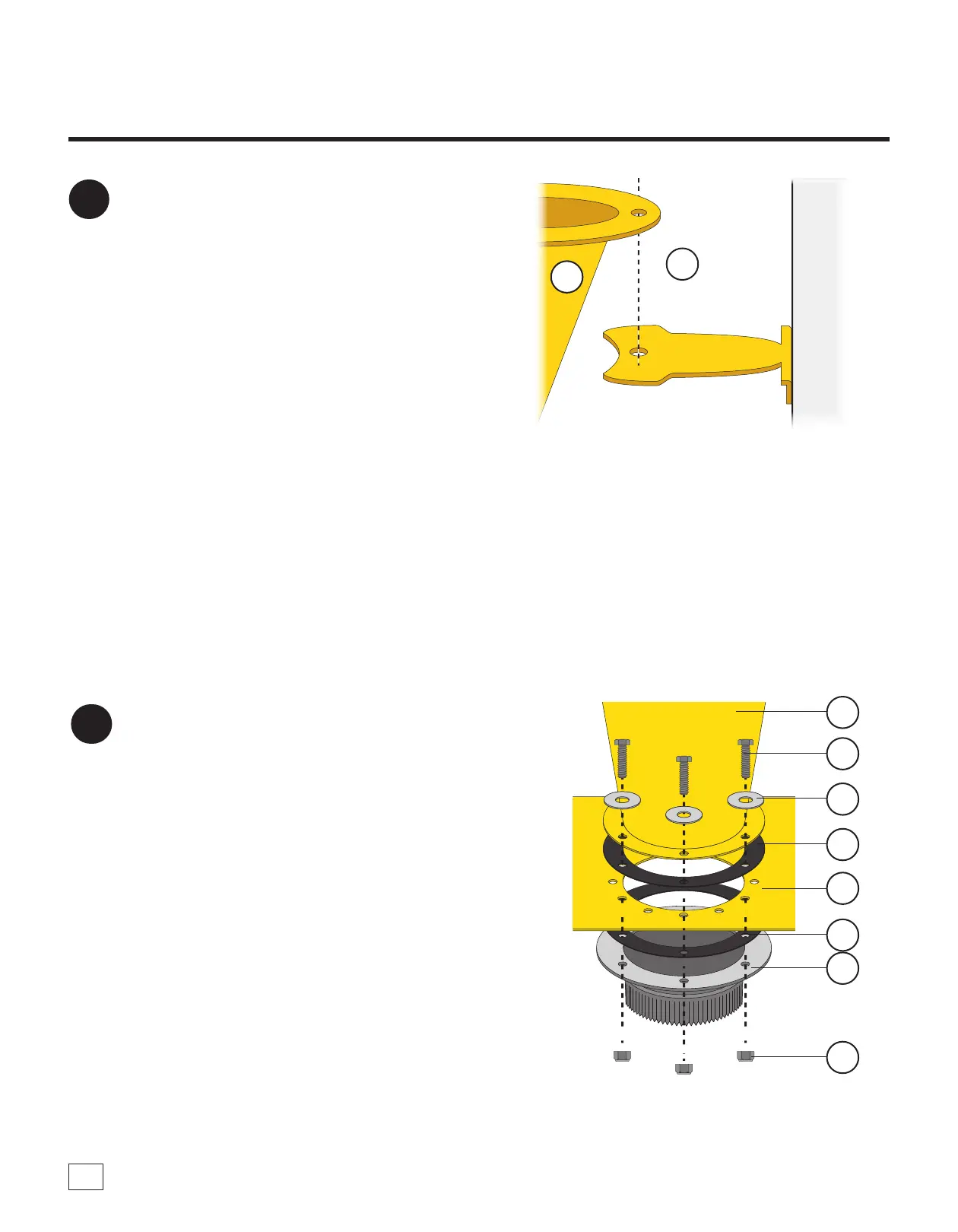
FIG. 11
E
G13
11
Align the Rear Support Brace (G13)
underneath the hole closest to the wall on the
upper ange of the Cyclone (E) [FIG 11].
Note: Ensure there is room between the Rear
Support Brace and the Cyclone's hole for the
Nylon Spacer (G12) used in Step 13.
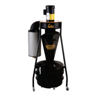
FIG. 14
G4
G3
G14
G5
E
12
Connect the Cyclone (E) and the 5" Collared
Flange (G14) to the Wall Bracket (F) with a
Flange Gasket (G3) placed between each one.
Secure together using six Hex Head Bolts
(G4), six Flat Washers (G5), and six Nylock
Nuts (G6) [FIG. 14].
G3
G6
F