G19
M
oneida-air.com 23
23
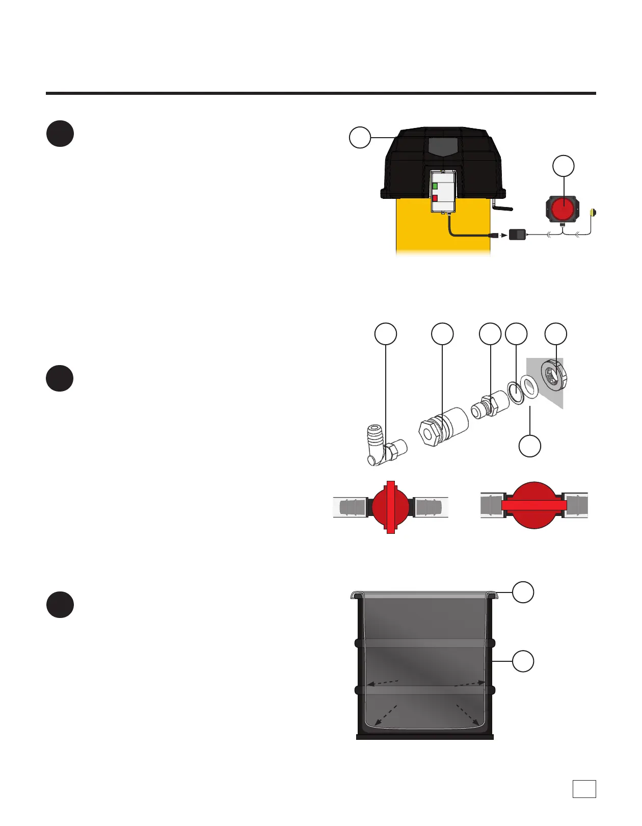
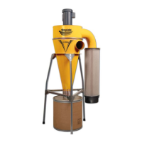
Connect the Dust Sentry (J) to the smaller
power cord on the Motor Assembly's (A)
magnetic starter. e Dust Sentry (J) should
be mounted in a highly visible area using
adhesive strips or the Sentry's two mounting
holes [FIG. 23].
• Refer to the Dust Sentry Installation Sheet
for more information.
Note: e Dust Sentry's location is limited by
the two wires extending from the Strobe Light.
e Infrared Sensor must have sucient length
to install in the pre-cut hole on the Steel Drum
Lid (K).
Assembly Instructions (Continued)
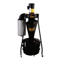
24
Install the Quick-Disconnect Kit (G18) onto
the pre-drilled hole near the bottom section of
the Drum (L) [FIG. 24a].
• Refer to the Quick Disconnect Installation
Sheet for more information.
Note: If you are not using the automatic bag
holding feature of the system, the Switch Valve
of the Tube Assembly (G16B) MUST be in the
closed position [FIG. 24b].
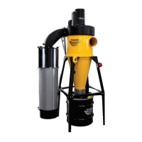
25
Place a Liner Bag (G19) inside the Drum (L).
Take care to ensure that the Liner Bag (G18) is
fully expanded to the inside of the drum and
so that the upper edge of the Liner Bag (G18)
is folded out and over the lip of the drum [FIG.
25].
Note: If you are not using the automatic bag
holding feature of the system, the Valve of
the Tube Assembly MUST be in the closed
position.
G18F
G18E
G18DG18CG18BG18A
FIG. 23
FIG. 25
A
J
FIG. 24b
FIG. 24a
Closed Open