FIG. 26
FIG. 27
Oneida Air Systems, Inc.24
Assembly Instructions (Continued)
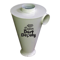
27
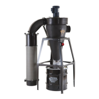
Install the Dust Sentry Infrared Sensor (J)
to the Drum Lid's (K) pre-cut hole [FIG. 27]
Ensure that the additional hole is sealed with
the Plug (G20).
• Refer to the Dust Sentry Installation Sheet
for more information.
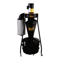
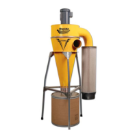
28
Seal the Drum (L) closed using the provided
clamp [FIG. 28].
infrared Dust Sentry
ultrasonic Dust Sentry
Mini-G Window
Collar for Flex Hose
Infrared
Sensor Hole
Window
Discharge
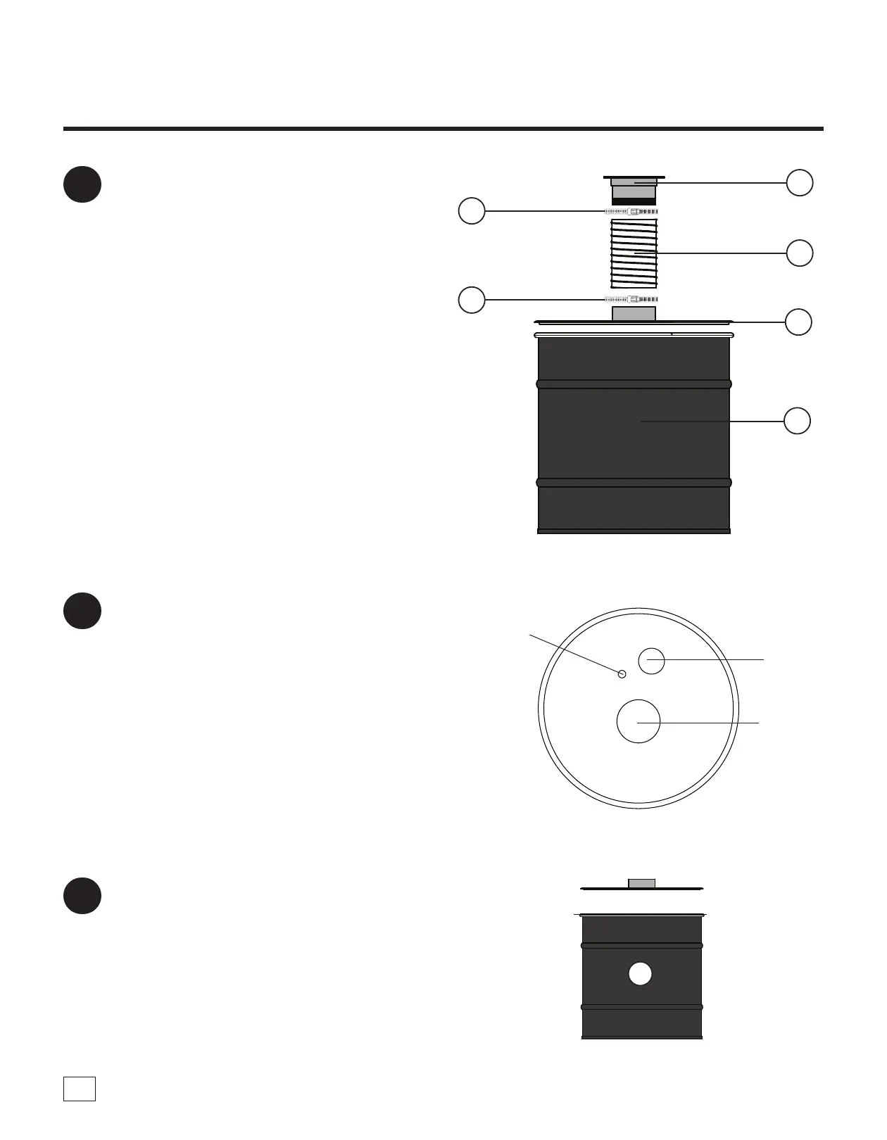
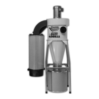
26
Attach the Flex Hose (H) to the inlet on the
Drum Lid (K) and secure it in place using a
Hose Clamp (G15). Loosely place a second
Hose Clamp (G15) onto the hose and then
move the Drum (L) underneath the Wall
Bracket (F). Connect the Flex Hose (H) to the
Collar (G14) and secure in place using the
additional Hose Clamp (G15) [FIG. 26].
Note: For the 55-Gallon, the lid's collar is oset
from the center. e Drum should be rotated so
that the inlet is closest to the wall to provide the
best visibility to the ll viewing window on the
Drum Lid (K).
H
K
L
G14
G15
G15
Clamp
L
FIG. 28