Do you have a question about the Onkyo A-9030 and is the answer not in the manual?
Critical components for safety: fire and electric shock risk. Use specified part numbers.
Procedure for preparing the unit for shipping, including memory initialization and initial settings.
Initialize unit memory by pressing PURE DIRECT and Standby buttons simultaneously.
Configure initial settings: selector, speakers, tone, RI mode, and standby.
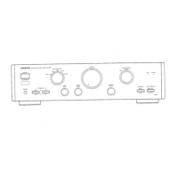
Verify speaker relays and sound output with headphone jack insertion.
Check remote control functions and RI mode operation.
Test Audio Sense function with varying input signal levels.
Test 12V trigger input/output for auto power control.
Test voltage protection by applying DC inputs and checking relay.
Test current protection by connecting loads and observing relay response.
Instructions for entering test modes and performing operational checks.
Diagram of external assembly and cover removal.
Illustration of front panel and internal chassis component assembly.
Diagram of heatsink, transformer, and circuit board assembly.
Overall block diagram showing main functional modules and signal paths.
Detailed schematic of audio input and processing circuits.
Schematic of power amplifier stages and output circuits.
Schematic for display control and front panel indicator circuits.
Schematic of digital inputs, DAC, and control processor circuits.
List of components shown in exploded views, organized by assembly.
Continued listing of parts for screws, coils, and connectors.
Parts list related to the packaging and shipping materials for the unit.
List of semiconductor components on the main PCB (U001).
Continuation of semiconductor component list for the main PCB (U001).