EasyManua.ls Logo

Onkyo TX-SR601/E User Manual

Onkyo TX-SR601/E
81 pages
To Next Page IconTo Next Page
Page #1 background imageLoading...
Page #1 background image
TX-SR601/E
SERVICE MANUAL
SERVICE MANUAL
Ref. No. 3773
062003
120V AC, 60Hz
230-240V AC, 50Hz
120/220-230V AC, 50/60Hz
220-230V AC, 50Hz
AV RECEIVER
MODEL
TX-SR601/E
Black, Golden and Silver models
BMDD,BMDC,SMDC
BMPP,SMPP,BMPA,SMPA
BMWT,GMWT,GMWR,GMWQ
GMGK
STANDBY/ON
PHONES
REC OUT ZONE 2
OFF
VIDEO 4
INPUT
DIGITAL
VIDEO 3
TAPE
TUNER
VIDEO
4
SURROUND
DSPSTEREO
DISPLAY
MEMORY
DIRECT
VIDEO 2
DVD
VIDEO
1
AUDIO
SELECTOR
CLEAR
FM MODE
LISTENING MODE
TUNI
NG
PRESET
MASTER VOLUME
RETURN
ENTER
AUDIO
ADJUST
SETUP
OFF
ON
POWER
RT/PTY/ TP
VCR 2VCR 1
LEVEL
S VIDEO
VIDEO
AUDIO
LR
STAND
B
Y
C
D
SAFETY-RELATED COMPONENT
WARNING!!
COMPONENTS IDENTIFIED BY MARK ON THE
SCHEMATIC DIAGRAM AND IN THE PARTS LIST ARE
CRITICAL FOR RISK OF FIRE AND ELECTRIC SHOCK.
REPLACE THESE COMPONENTS WITH ONKYO
PARTS WHOSE PART NUMBERS APPEAR AS SHOWN
IN THIS MANUAL.
MAKE LEAKAGE-CURRENT OR RESISTANCE
MEASUREMENTS TO DETERMINE THAT EXPOSED
PARTS ARE ACCEPTABLY INSULATED FROM THE
SUPPLY CIRCUIT BEFORE RETURNING THE
APPLIANCE TO THE CUSTOMER.
Page 1
Question and Answer IconNeed help?

Do you have a question about the Onkyo TX-SR601/E and is the answer not in the manual?

Onkyo TX-SR601/E Specifications

General IconGeneral
BrandOnkyo
ModelTX-SR601/E
CategoryReceiver
LanguageEnglish

Summary

Safety Related Component Warning

Specifications

Amplifier Section Specifications

Details continuous power output, distortion, input sensitivity, and frequency response.

Tuner Section Specifications

Details FM and AM tuning range, sensitivity, selectivity, and distortion.

General Specifications

Covers power supply, power consumption, dimensions, and weight.

Service Procedures

Replacing Fuses

Provides part numbers and descriptions for replacement fuses.

Safety Check Out

Details leakage current check for U.S.A. models.

Front Panel Controls Overview

Front Panel Facilities

Power Switch and Standby/On Button

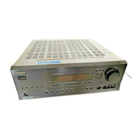
Describes the main power switch and standby/on button functions.

Display and Input Indicators

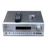
Explains display button, RT/PTY/TP, and dimmer functions.

Front Panel Facilities (Continued)

Rear Panel Connections

Remote Controller Functions (RC-533M)

Remote Controller Functions (RC-533M) (Continued)

Block Diagram: Digital Audio Input/Output

Block Diagram: Multichannel Input and Power Amplifier

Schematic Diagram 1: Front Panel Section

Schematic Diagram 1: Front Panel Section (Continued)

Schematic Diagram 3: Driver Section

Schematic Diagram 3: Driver Section (Continued)

Schematic Diagram 2: DSP and Main Microprocessor

Schematic Diagram 2: DSP and Main Microprocessor (Continued)

Schematic Diagram 1-1: Front Panel Section

Schematic Diagram 4: Power Amplifier Section

Schematic Diagram 4: Power Amplifier Section (Continued)

Schematic Diagram 5: Power Supply and Speaker Terminal Sections

Schematic Diagram 5: Power Supply and Speaker Terminal Sections (Continued)

Schematic Diagram 6: Video and Bus Line Sections

Schematic Diagram 6: Video and Bus Line Sections (Continued)

IC Block Diagrams and Descriptions: TC9274F-020

IC Block Diagrams and Descriptions: BD3811K1

IC Block Diagrams and Descriptions: LC74763-9836

IC Block Diagrams and Descriptions: LC72723M

IC Block Diagrams and Descriptions: BD3812F

IC Block Diagrams and Descriptions: TC9164AF

IC Block Diagrams and Descriptions: CS42518

Main Microprocessor Terminal Description

Main Microprocessor Terminal Description (Continued)

Adjustment and Confirmation Procedures 2

Adjustment and Confirmation Procedures 1

Related product manuals