24
USE AND MAINTENANCE INSTRUCTIONS
MANUALE DI USO E MANUTENZIONE
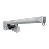
Box crane
Gruette da box
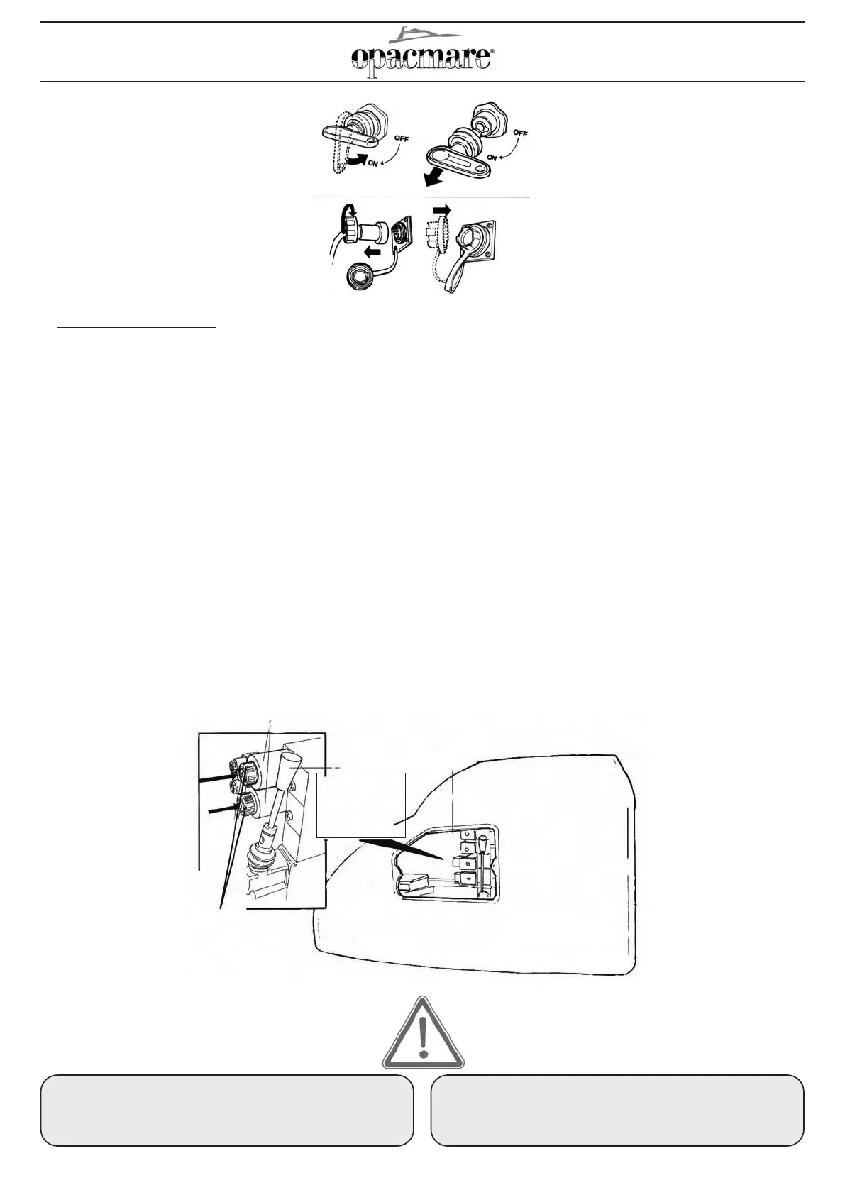
a) Turn off the main switch of the crane (if
installed) by turning the red key to the OFF
position, and then remove the key, which
must be kept in a safe place by a
responsible person;
b) Disconnect the remote-control unit from
the crane base and store it in a dry place;
c) Close the remote-control connector
socket on the crane base with the rubber
protection cap.
a) Disinserire il sezionatore generale della
gruetta (quando installato) ruotando la
chiave rossa in posizione OFF e toglierla
dalla sede (la chiave deve essere custodita
da una persona responsabile in un luogo
sicuro);
b) Scollegare il telecomando dalla base della
gruetta e riporlo in luogo asciutto;
c) Chiudere con il tappo di protezione in
gomma la presa del telecomando che si
trova alla base della gruetta.
DO NOT CONNECT OTHER ELECTRONIC EQUIPMENT TO
THE OPACMARE ELECTRONIC SYSTEM, UNLESS
SPECIFICALLY AGREED UPON WITH THE COMPONY,
SUBJECT TO FORFEITURE OF GUARANTEE RIGHT.
E’ SEVERAMENTE VIETATO COLLEGARE ALTRE
APPARECCHIATURE ELETTRONICHE ALL’ELETTRONICA
OPACMARE SE NON CONCORDATO CON L’AZIENDA,
PENA LA DECADENZA DELLA GARANZIA.
solenoid valve
opening pins
puntalini di apertura
elettrovalvole
electro-valves
elettrovalvole
Leva di comando
manuale
ã Manovre di emergenza
In caso di avaria ai sistemi elettrici o elettronici del tenderlift è pos-
sibile manovrare manualmente la centralina oleodinamica che è
dotata di una pompa manuale di emergenza; le elettrovalvole pos-
sono essere aperte manualmente.
Nel caso in cui la centralina fosse montata fuori dalla base della
gruetta, occorre per prima cosa individuarne la posizione nei loca-
li dell’imbarcazione, nel caso la centralina fosse integrata nella
base occorre smontare la copertura in vetroresina della base.
Per portare l’olio in pressione agire con una mano sulla leva di
comando della pompa manuale e con l’altra mano mantenere pre-
muto il puntalino di apertura manuale dell’elettrovalvola come illu-
strato nella figura utilizzando un utensile appropriato che non righi
la sede del cilindretto (Punta arrotondata Ø max 3 mm), così
facendo si aprirà la valvola, e pompando con la pompa manuale si
invierà l’olio in pressione al pistone desiderato (azionare più volte
la leva per eliminare l’aria e metter in pressione l’impianto).
La movimentazione sarà lenta ma efficace.
A fine manovra, nel caso di centralina integrata alla base, rimonta-
re correttamente le viti della base.
ã Emergency procedures
In the case of failure of the electrical or electronic systems of the
crane, it is possible to drive the hydraulic unit manually.
It is equipped with a manual emergency pump and the solenoid
valves can be opened and closed by hand.
In the case in which the hydraulic control unit was installed out of
the crane base, it is necessary locate the position on the boat, if
the hydraulic unit was positioned into the base, it is necessary
remove the resin cover of the crane base.
To pressurize the hydraulic fluid, press with one hand on the con-
trol lever of the manual pump and with the other hand press on the
cap of the manual electro-valve opening with a special tool, as
shown in the diagram (Round point Ø max 3 mm).
The valve will open and pumping on the manual pump, the pres-
surized oil will reach the right piston (the lever has to be moved
several times to eliminate and pressurize the system). In this case,
the crane movements will be slower but effective.
At the end of the operation, in case the hydraulic control unit is
located in the base, reassembly the screws of the base correctly.