Thermocode 2 Printer manual Version 2.04 January 2011 13
13
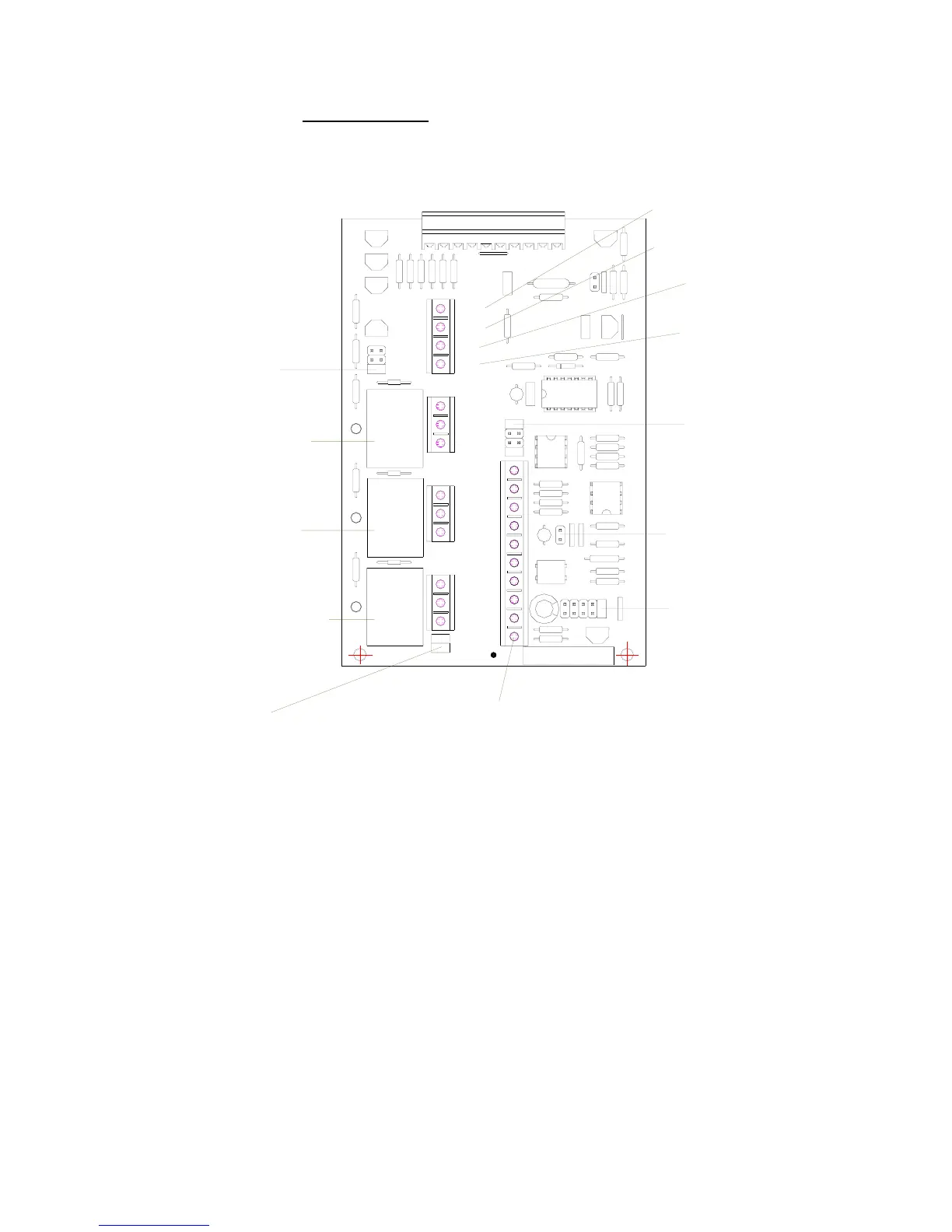
Power Supply
(I/O Board connections)
(fit Print Signal Selectors to positions "J" & "L" only)
Input (6 - 35 volt AC):- Connect wires to terminals 3 & 4, polarity unimportant.
(fit Print Signal Selectors to positions "J" & "L" only)
Input (9 - 50 volt DC):- Connnect wires to terminals 3 & 4, polarity unimportant.
(fit Print Signal Selector to "M" only as shown)
Voltage Free Connections:- Connect wires to terminals 1 & 2.
Print Signal Inputs
10
2 = "Ready"
1 = "fault & Ready" (Default)
Spare Link
Default Software Setting
0 = "fault"
RELAY
3
N/C
N/O
COM
1 = "Low Foil" (Default)
0 = "Start Machine"
1 = "Sequence" (Default)
0 = "Stop Machine"
Default Software Setting
Default Software Setting
C = Standard Relay
A = Reed Relay
Relay 1 Output Choice.
2 = "Ready"
B = Transistor
RELAY
RELAY
2
1
N/O
COM
N/C
N/C
N/O
COM
B
C
A
RR1
RR2
TRO
TRN
contact bounce. ie heavy
6
Print Signal Selector Link
duty relays or switches etc.
PCB 763068
1
3
2
4
5
JH MLK
Reed Relay Connection
(Max 350V ac/dc 0.75A, 1.5ms)
Reed Relay Connection
(Max 350V ac/dc 0.75A, 1.5ms)
Fit link for input signals with
Link E & F for "Falling Edge"
Link D & G for "Rising Edge"
Auxillary Contacts:-
(Rated 100v DC, 3 amp max.)
Transistor NPN output
(Link to the machine "O" volt)
Transistor "O" Volt.
8
7
9
D
F
G
E