Thermocode 2 Printer manual Version 2.04 January 2011 10
10
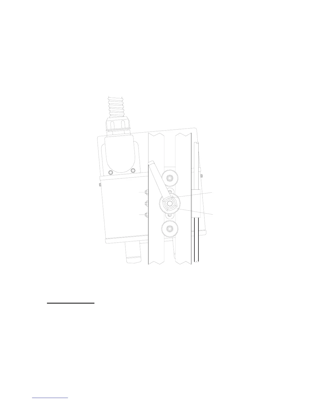
Alignment of right hand Printer to the Lower Roller Unit
A. Release the “
Clamp Handle
” by a quarter turn. (See below)
B. Adjust the “
Upper Screw B
”, undo by half a turn. (See below)
C. Adjust the “
Upper Screw A
”, do up by half a turn. (See below)
D. Lock up Clamp Handle.
E. Test a print an image, to show the printer is aligned to the Lower roller Unit.
CLAMP HANDLE
CLAMP WASHER
UPPER SCREW "A"
UPPER SCREW "B"
If the printer is aligned opposite to the above shown diagram, just reverse the adjustment
procedure. By Adjusting the “Upper Screw A” before “Upper Screw B”.
You may have to repeat the procedure to ensure the printhead is aligned to the lower Roller unit correctly.
Installation Notes
1. Installing the
Thermocode 53CR
printer in a Standard mounting frame may not be required, but please
check that all frame dimensional details needed are attained. It is very important that the alignment to the
print roller is correct (see pages 8, 9 & 52
2. frame details etc.)
3. Connect the printer and power supply using the interconnection lead supplied. The lead has been
specifically designed, so it cannot be fitted incorrectly. Please ensure that the plugs and sockets are
inserted fully before tightening the fixing screws. Orientation of the mounting plate can be changed, by
removing the two fixing screws. Then rotating the mounting plate.
4. Each installation must have an automatic print signal from the parent machine, this is normally a relay
(voltage free) or 24 Volt pulsed output signal.