Thermocode 2 Printer manual Version 2.04 January 2011 9
9
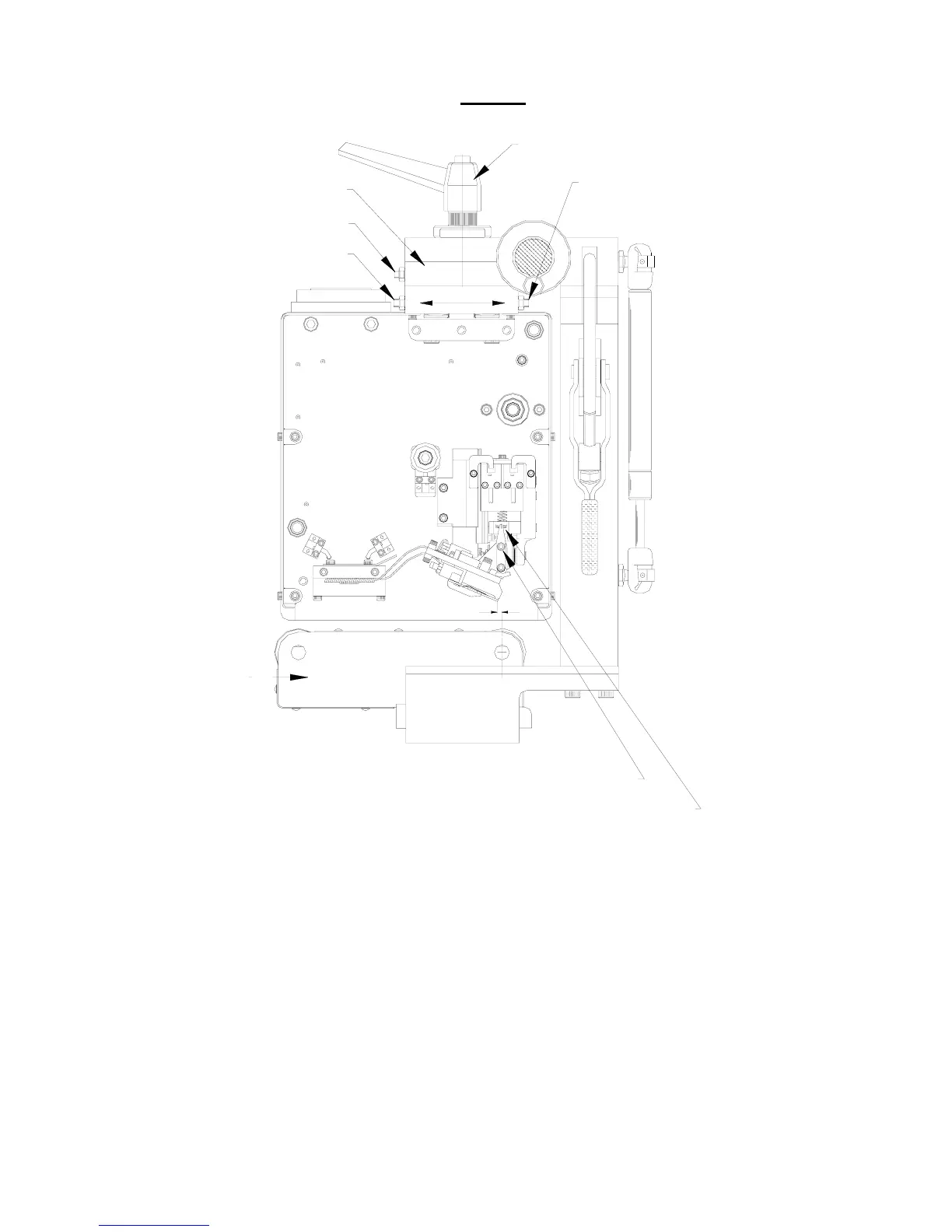
FIG 2B
PRINTHEAD SUPPORT ASSEMBLY
ADJUSTMENT
UPPER SCREWS A & B
LOWER ROLLER UNIT
LOWER SCREW D
LOWER SCREW C
CHECK PRINTHEAD ANGLE
CLAMP HANDLE
PRINTHEAD LOCKING SCREWS
CENTRE LINE ROLLER
1.00 mm
FIG. 2
Align the Printer to be adjusted correctly in the Standard frame, set the Printhead to be behind the print
roller centre-line at “
1.0 mm
” dimension. (See above)
A. Release the “
Clamp Handle
” by a quarter turn. (See above)
B. Adjust the “
Lower Screw D
”, undo by half a turn. (See above)
C. Adjust the “
Lower Screw C
”, do up by half a turn. (See above)
(Lower Screw C is the opposite side of the frame)
D. Lock up Clamp Handle. (Once correct, lock up lock nuts)