Thermocode 2 Printer manual Version 2.04 January 2011 7
7
INSTALLATION PROCEDURES
Installing the 53CR Continuous Printer on a Standard Continuous Frame
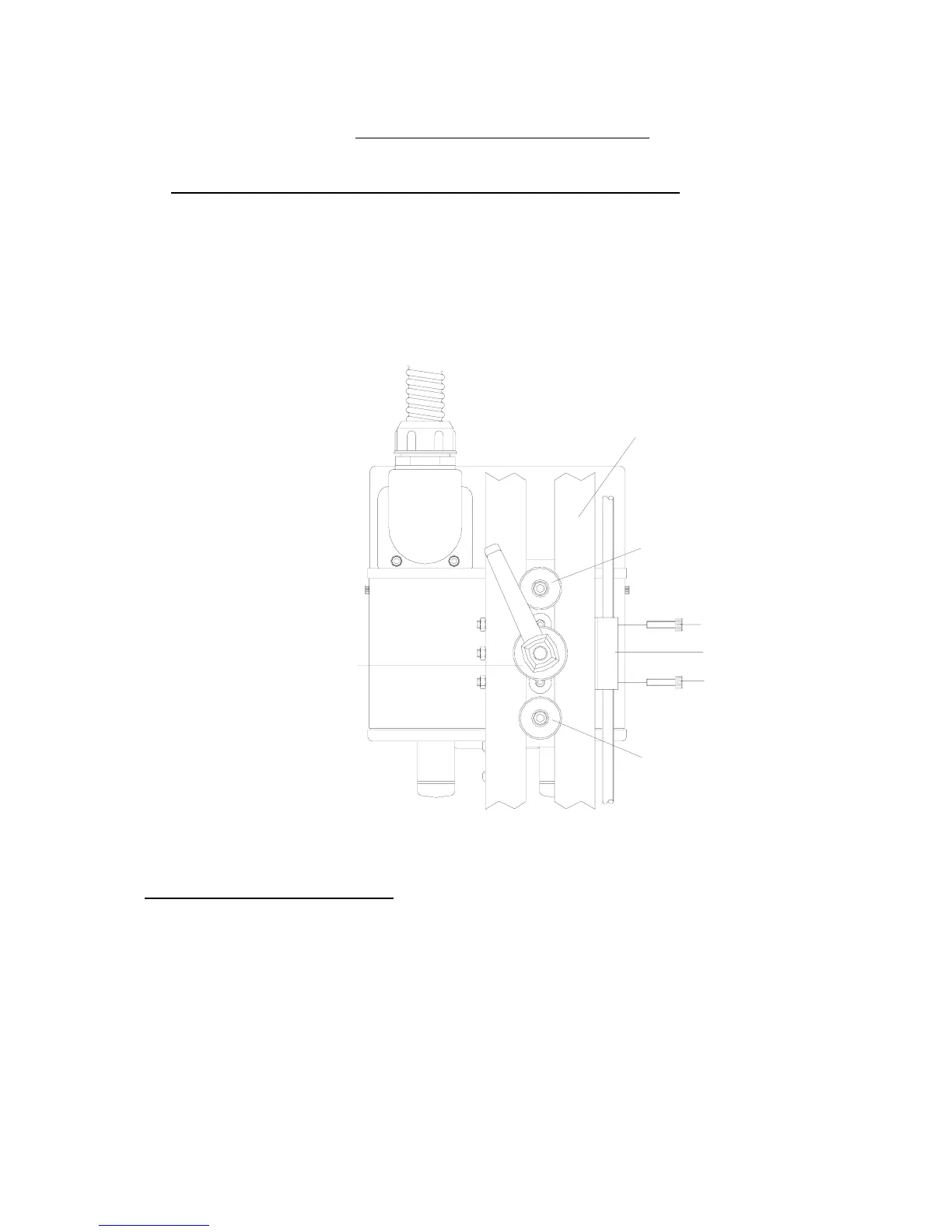
1. Install the right hand printer into the Standard Continuous frame, utilising the “
location sleeves
” and
then lock the “
clamp handle
” (see below)
2. Fit the retaining screws for the linear block adjustment. (See below)
LOCATION SLEEVE & FIXING SCREW
LOCATION SLEEVE & FIXING SCREW
CLAMP HANDLE & WASHER
LINEAR ADJUSTMENT BLOCK
LINEAR BLOCK FIXING SCRE
FRAME TOP SLOTTED BAR
Checking the Printhead Angle
1. Check the “
printhead angle
” has been set correctly remove the magazine to visually check the
mechanical angle setting. Within the mini-display unit, select the “
Service Menu”
number 4
Print
head data
, and check the printhead angle has been set correctly.
If the angle does not correspond, release the “
Printhead Locking Screws
” and adjust until the
pointer is set correctly (See fig 2a Page 8) It may be necessary to switch off all electrics and
remove the printer to a well-lit area to carry out this fine adjustment.