- 27 -
optek-Manual--1004-2001-02--AF16-US-2011-01-04
www.optek.com
Connection to converter C4000
Note!
Detailed information on the connection of the sensor to a C4000-series
converter is given in the instruction manual of the converter. There you can as
well find the corresponding wiring plans.
Connection to the
converter
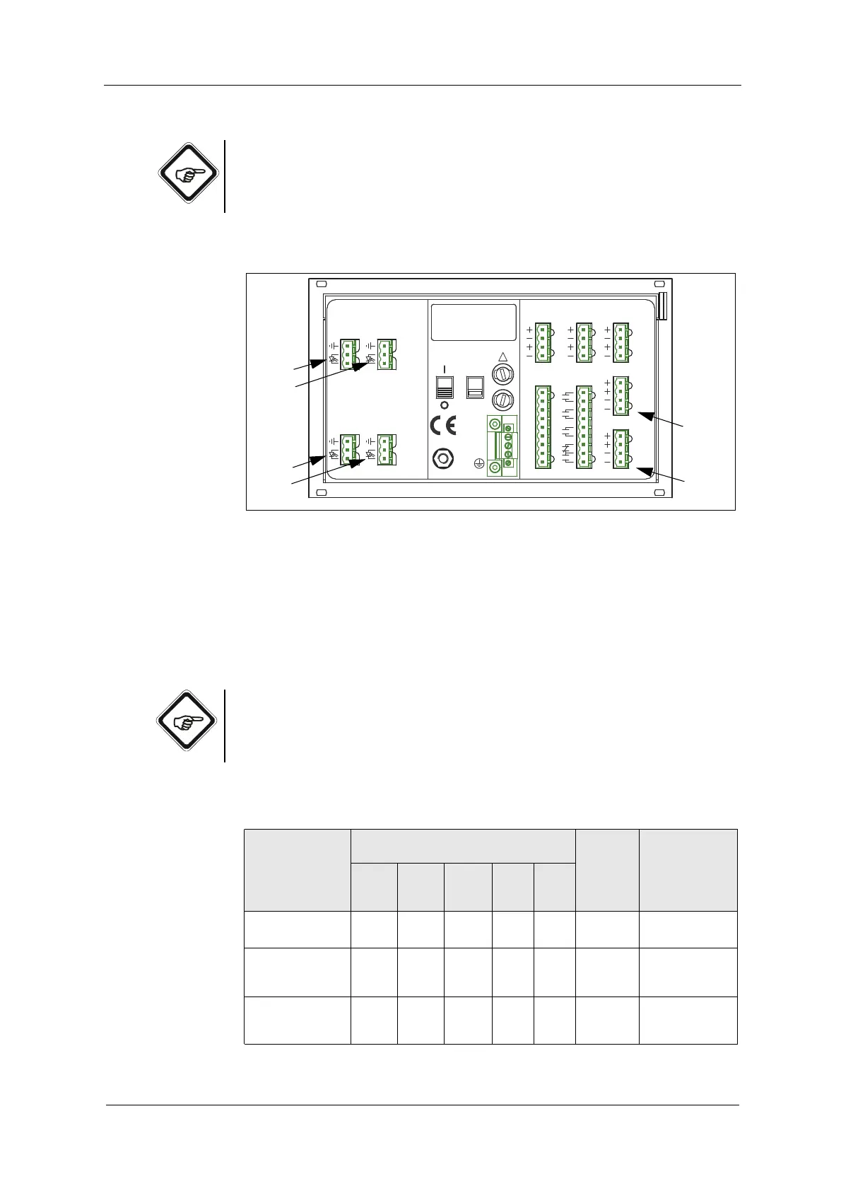
The following connections are on the back of the converter:
Fig. 21 Detector inputs and lamp outputs considering converter C4422 as example
Letters stand for
• A – D detector inputs
• E – F connections for lamp outputs
Connections depend on the equipment of your converter and on the number of
sensors you wish to connect.
Note!
Do not use other detector inputs and lamp outputs than given in table 16, even
if in some cases other combinations are possible. Thus, danger of mixing inputs
and outputs up is minimized.
Tab. 16 Connections
Number of
sensors
sensor type
Detector input connection of the
converters
Lamp
output
Cable set
standard length
up to
C4101
C4121
C4151
C4201
C4221
C4251
C4202
C4222
C4252
C4322
C4352
C4422
C4452
1 sensor
AF16
A
A
A
A
A
E
100 m / 328 ft.
*
2 sensors
AF16
AF16
A
C
A
C
A
C
E
F
100 m / 328 ft.*
2 sensors
AF16
AS16 / AS16-BT
A
C
A
C
A
C
E
F
100 m / 328 ft.*
50 m / 164 ft.
20 2119
DETECTOR INPUTS
[C]
3
4
5
3
4
[D]
5
DETECTOR INPUTS
[A]
2
5
1
2
5
1
[B]
4 - 20 mA
OPTEK - DANULAT
REMOTE IN
R1
PA
M6
N
PE
L
R7
R8
RR
R4
R5
R6
R2
R3
115 / 230 V, 50 / 60 Hz, 50 VA
115 / 230 V, T 1,6 A
230V
!
24 V DC
IN 1, 2
acc. to
6
1031
MADE IN GERMANY
37
38
39
34
35
36
32
33
16
17
18
13
14
15
11
12
6
7
7
LAMP [F]
6
7
7
acc. to
cable
length
V DC
cable
length
0 / 4 - 20 mA
OUT 1, 2
24 V AC / DC
RELAY OUT
22
23
24
21
41
42
43
40
46
47
45
44
LAMP [E]
6
OUT 3, 4
V DC