6
2 .Structure and Basic Principles
2.1 General Structure
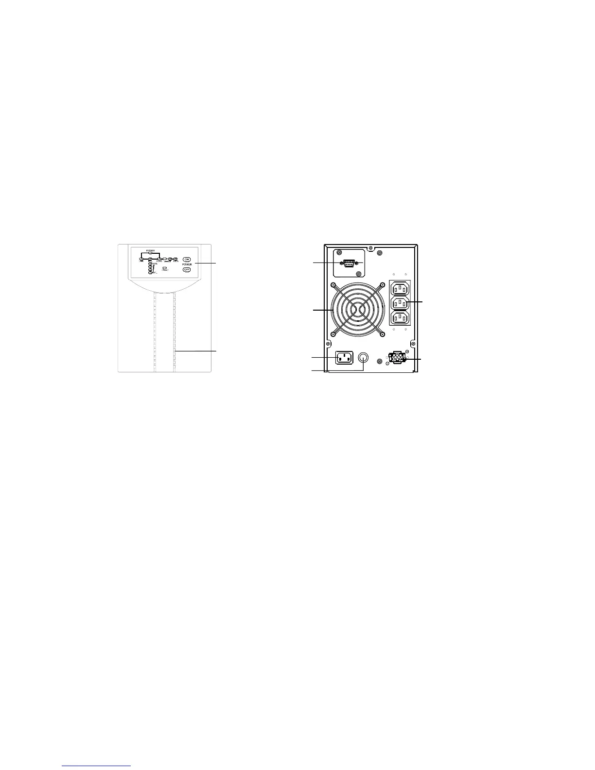
2.1.1 DS1000E Series Front Panel, Rear Panel Structure
Front and rear panel structure of the main unit of DS1000E and DS1000EL are
illustrated in Fig. 2-1.
AC Input Socket
DC Input
AC Output
Sockets
Fuse
RS232
Port
Fan
FUSE
AC INPUT
DC INPUT
AC
OUTPUT
RS232
UPS Operation
Status Indicator
Light
Air intake hole
on front panel
(Front Panel) (Rear Panel)
Fig. 2-1 DS1000E Series Front Panel and Rear Panel Structure
Upside of DS1000E front panel is provided with operation status indicator light
and power on/off button, as shown in Figure 2-2. Shape of status indicator light
and power on/off button on DS2000E and DS3000E panels are the same as
shown in Figure 2-2. Inside which operation status indicator lights include:
commercial power light (LINE), bypass light (BYPASS), inversion light
(INVERTER), battery status light (BATTERY), load status light (LOAD), fault
light (FAULT). Load status light and battery status light are respectively
composed of four indicator lights, each standing for 25% of total capacity.