DS-E Series(1~6KVA)User’s Manual
11
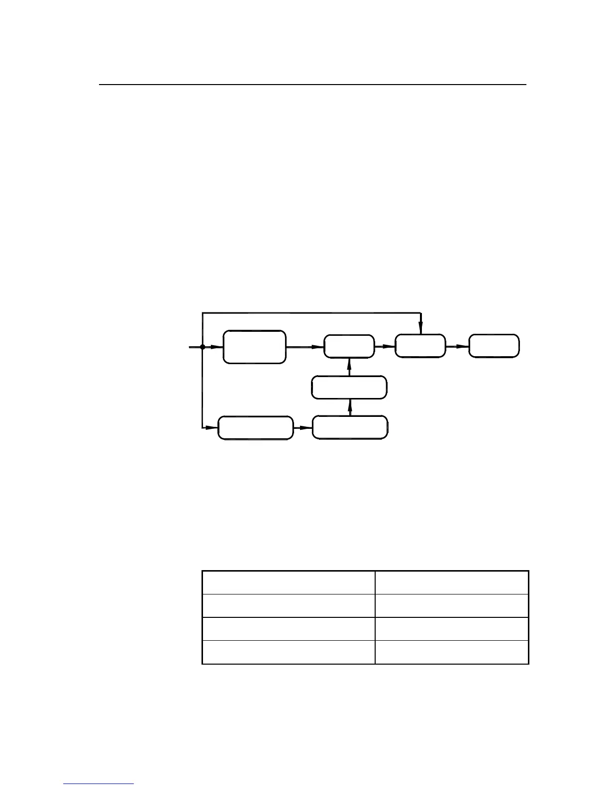
2.2 Basic Principles
When commercial power is normal, DS-E series UPS input, through PFC,
increases the voltage to ± 360V stabilized DC voltage, which supplies DC/AC
inverter and transmits stable AC 230V, while at the same time completing the
charging of the battery. When commercial power is abnormal, the battery
increases the voltage through DC/DC to ± 360V DC voltage and supplies
DC/AC inverter.
UPS principle lock diagram is shown in Fig. 2-5. DC/AC inverter adopts
half-bridge structure, while DC/DC voltage increase adopts push-pull or
BOOST circuit. PFC is active power-factor correction circuit controlled by
UC3854, while CHARGER is complete isolation type charger.
CHARGE
PFC AC/DC
SW
BATTERY
DC/DC
DC/AC
LOAD
230Vac
Fig. 2-5 UPS Basic Principle Block Diagram
Corresponding relations of pins for the RS232 serial ports of this series UPS
and those of general PC are shown in Table 2-1.
Table 2-1: Corresponding relations of pins for the RS232 serial ports of this
series UPS and those of general PC:
Communication RS232 Interface for UPS General RS232 Interface
9 (3) 2 (Receive)
6 (2) 3 (Deliver)
7 (5) 5 (Ground)