DS-E Series(1~6KVA)User’s Manual
8
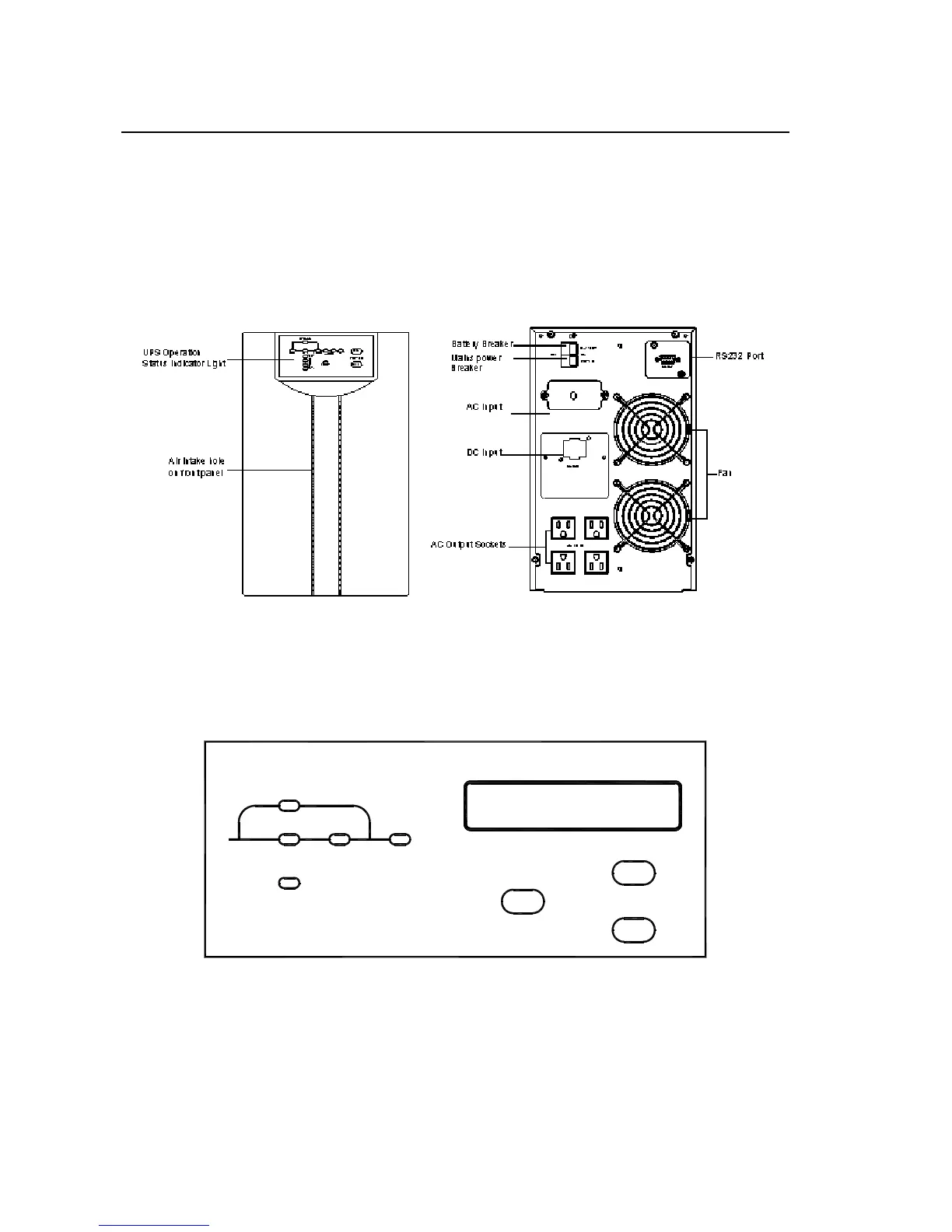
commercial power input switch and switch for storage battery. The upper switch
is for storage battery, and the lower one is AC input switch. Input line bank and
output line bank each has three connecting terminals, which in turn, from left to
right (rear view), are live wire (L), neutral wire (N) and ground wire (GND).
(Front Panel) (Rear Panel)
Fig. 2-4 DS2000/3000E Series Front Panel and 120V Rear Panel Structure
2.1.4 DS6000E Series Display Interface, Front Panel, Rear Panel Structure
INV.LINE
BYPASS
OUTPUT
SELECT
ON
OFF
FAULT
INPUT
①②
③
④
⑤
⑥
⑦
⑧
⑨
Fig. 2-3 DS6000E Series Display Interface
Illustration:
① “LINE” : When commercial power is normal, light on, abnormal off.