DS-E Series(1~6KVA)User’s Manual
7
BYPASS
INVLINE
LOAD 100%
100%
BAT
ON
POWER
OFF
FAULT
Fig. 2-2 DS1000E Panel Indicator
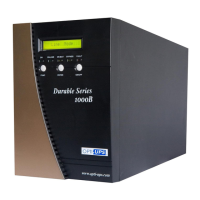
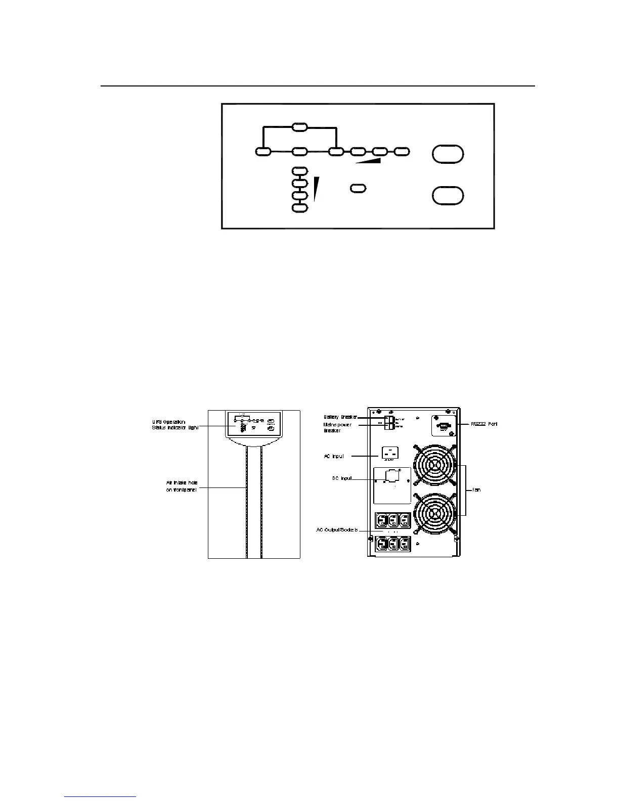
2.1.2 DS2000E Series Front Panel, Rear Panel Structure
Front and rear panel structure of the main unit of DS2000E and DS2000EL are
illustrated in Fig. 2-3. Inside which the switch on rear panel is composed of
switch for commercial power input and switch for storage battery. The upper
switch is for storage battery, and the lower one is for commercial power input.
(Front Panel) (Rear Panel)
Fig. 2-3 DS2000/3000E Series Front Panel and 230V Rear Panel Structure
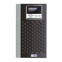
2.1.3 DS3000E Series Front Panel, Rear Panel Structure
Front and rear panel structure of the main unit of DS3000E and DS3000EL are
illustrated in Fig. 2-4. Inside which the switch on rear panel is composed of