OPTIMUM
MASCHINEN - GERMANY
Version 1.0.1 dated 2018-01-31 Page 41Translation of the original instructions
TM4010 | TM4010D GB
TM4010_TM4010D_GB_4.fm
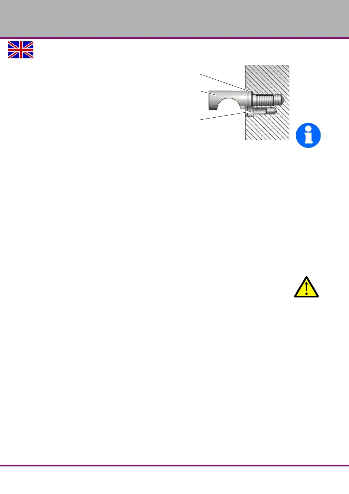
Adjusting the Camlock bolts to the workpiece holder
Detach the safety screw.
Turn the Camlock bolt by one complete
revolution
in or out, according to the correction nec-
essary.
Mount the safety screw
INFORMATION
The reference mark on each Camlock bolt
serves as orientation for the correct adjust-
ment.
Img.4-7: Camlock seat
4.13.2 Lathe chuck
During turning, the workpiece is subject to cutting forces, weight forces and unbalance forces
which have to be absorbed by a sufficiently strong clamping force. Massive workpieces with
higher degrees of stiffness lead to a considerable loss of clamping force. This loss of clamping
force is lower for thin-walled, distortion-sensitive workpieces with less stiffness.
The maximum rotational speed of a lathe chuck may only be applied at maximum actuating
force and with perfectly working chucks.
Lathe chucks must be designed for the maximum rotational speed of the machine, the permissi-
ble lathe chuck speed with respective jaws and/or top jaws, as well as the maximum measured
static clamping force at maximum introduced force must be specified in the operating instruc-
tions for the lathe chuck or be indicated on the lathe chuck itself. Replacement lathe chucks
must comply with EN 1550 standards. The minimum distance to the machine bed must not be
less than 25 mm.
WARNING!
Do not clamp any workpieces that exceed the permitted chucking capacity of the lathe
chuck. The clamping force of the chuck is too low if its capacity is being exceeded. The
clamping jaws may loosen.
Only use lathe chucks designed for the speed of the machine.
Do not use lathe chucks with an external diameter that is too large.
Please ensure that lathe chucks are manufactured to EN 1550 standards.
4.13.3 Speed information, maintenance recommendations, reference speed in accordance
with DIN 6386
The reference speed is the number of rotations, at which the mathematical centrifugal force
with the corresponding jaw design correlates with the greatest tensioning force when the
machine is at a standstill. The reference speed applies for jaws mounted inside in tiers,
whereby they must not protrude past the outer diameter of the chuck.
At the determined reference speed, 1/3 of the tensioning force which is available when the
machine is at a standstill, is available for clamping the workpiece. The prerequisite is that the
clamping chuck is in proper working order.
In general, the labels on the clamping jaws and lathe chuck (perm. speed, max. turning diame-
ter, ...), the information in the respective lathe chuck operating instructions and, for special
jaws, the additional information on the respective drawing must be observed.
Reference
mark
Camlock
Bolt
Lock screw
 Loading...