HD20/HD200X/HD2200/HD20LV/HD21/HD23
Condential 2-8
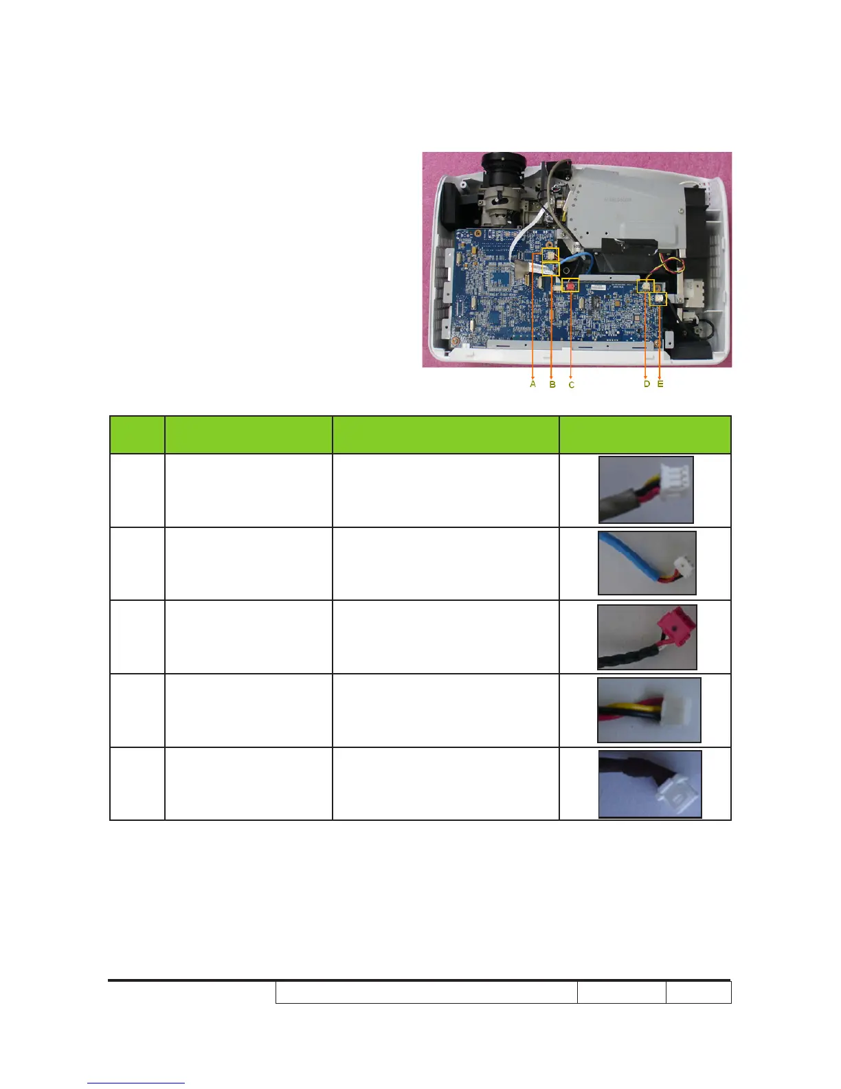
Note: - Make sure cables plug into the correct
ports when assembling the unit.
Please refer to the below table details of
each connector on Main Board.
Item
Male Connector
on Main Board
The key feature Figure
A FRONT IR
Compose of Black/Yellow/Red
Wire and Gray tube(3 pin)
B BLOWER
Compose of Black/Yellow/Red
Wire and Blue tube(3 pin)
C PHOTO SENSOR BD
Compose of Black/White/Red
Wire, Red Connector and Black
tube(3 pin)
D SYSTEN FAN
Compose of Red/Yellow/Black
Wire (3 pin)
E LAMP DRIVER Black wire tube (5 pin)