Electrical Installation 57-
4 Electrical Installation
4.1 Cable Connections
For the electrical installation of the CT please open at first the cover of the electronic box (4 screws). Below
the display are the screw terminals for the cable connection.
4.1.1 Designation [models LT/ G5/ P3/ P7]
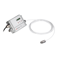
Opened LT/ G5/ P3/ P7 electronic box with terminal
connections
Ground (0 V) of power supply
Ground (0 V) of internal in- and outputs
Analog output head temperature (mV)
Analog output thermocouple (J or K)
Analog output object temperature (mV or
mA)
Alarm 2 (Open collector output)
3 VDC, switchable, for laser-sightingtool
Ground (0 V) for laser-sightingtool
w ww . . co m
information@itm.com1.800.561.8187