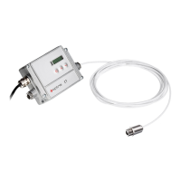
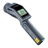
CT sensors can be optionally equipped with an USB-,
RS232-, RS485-, Profibus DP-*, Modbus RTU-* or Ethernet-
interface.
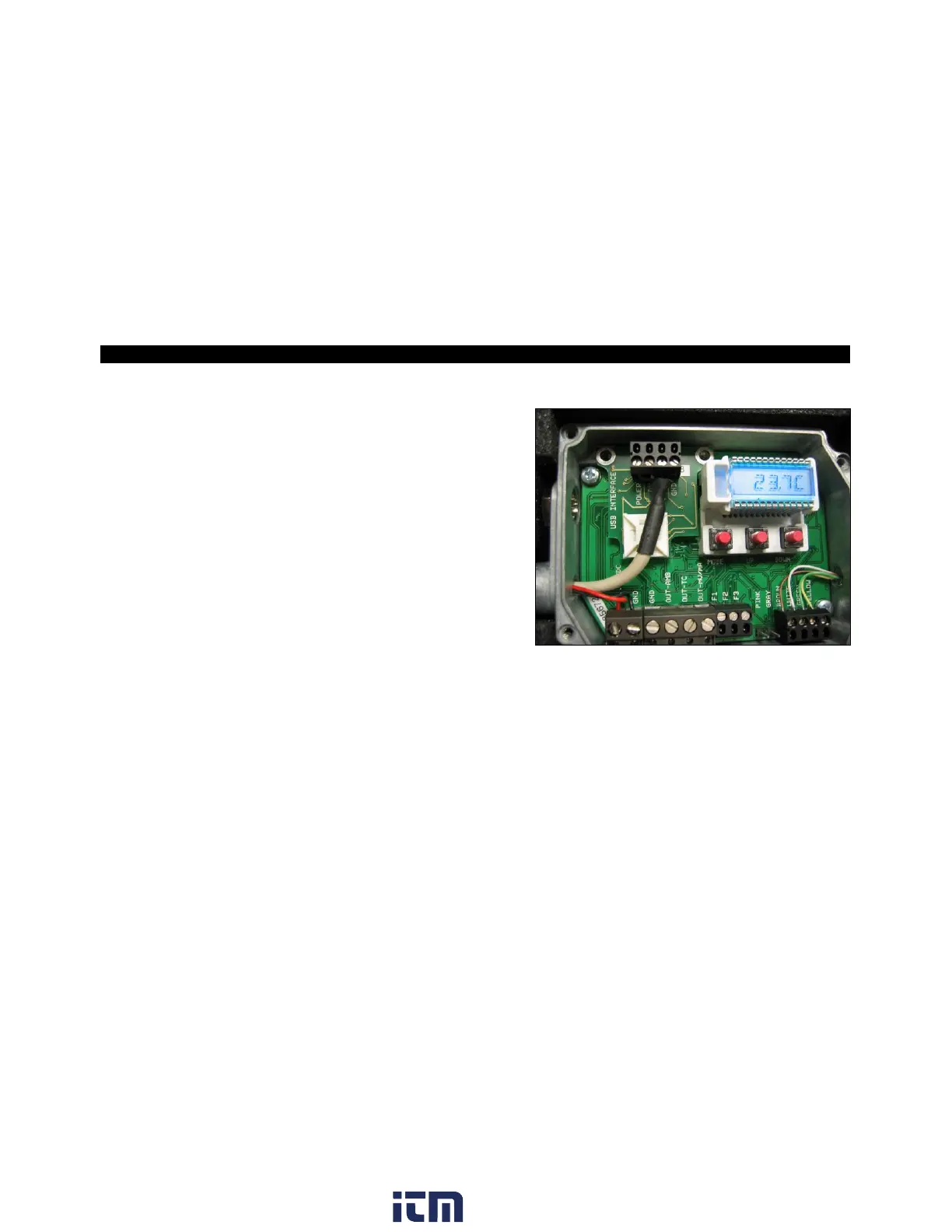
If you want to install an interface, plug the interface board
into the place provided, which is located beside the display.
In the correct position the holes of the interface match with
the thread holes of the electronic box. Now press the board
down to connect it and use both M3x5 screws for fixing it.
Plug the preassembled interface cable with the terminal
block into the male connector of the interface board.
* Not for CT 4M available
The Ethernet interface requires at minimum 12 V supply voltage.
Please pay attention to the notes on the according interface manuals.
5.3 Relay Outputs
The CT can be optionally equipped with a relay output. The relay board will be installed the same way as the
digital interfaces. A simultaneous installation of a digital interface and the relay outputs is not
possible. The relay board provides two fully isolated switches, which have the capability to switch
max. 60 VDC/ 42 VAC
RMS
, 0,4 A DC/AC. A red LED shows the closed switch.