Identifying a Faulted ZS4-4 Memory Module
location of the memory module in the controller picture, click on the module ID.
To view details about the faulted module, click its information icon and then click
Active Problems.
2.
Shut down the controller using one of the power-off methods described in
“Powering Off the Controller” on page 50.
3.
Disconnect the AC power cords from the rear panel of the storage controller.
Caution - Because 3.3 VDC standby power is always present in the system, you must unplug
the power cords before accessing any cold-serviceable components.
4.
Extend the controller from the rack as described in “Extending the Storage
Controller from the Rack” on page 51.
5.
Remove the top cover as described in “Removing the Top Cover” on page 52.
6.
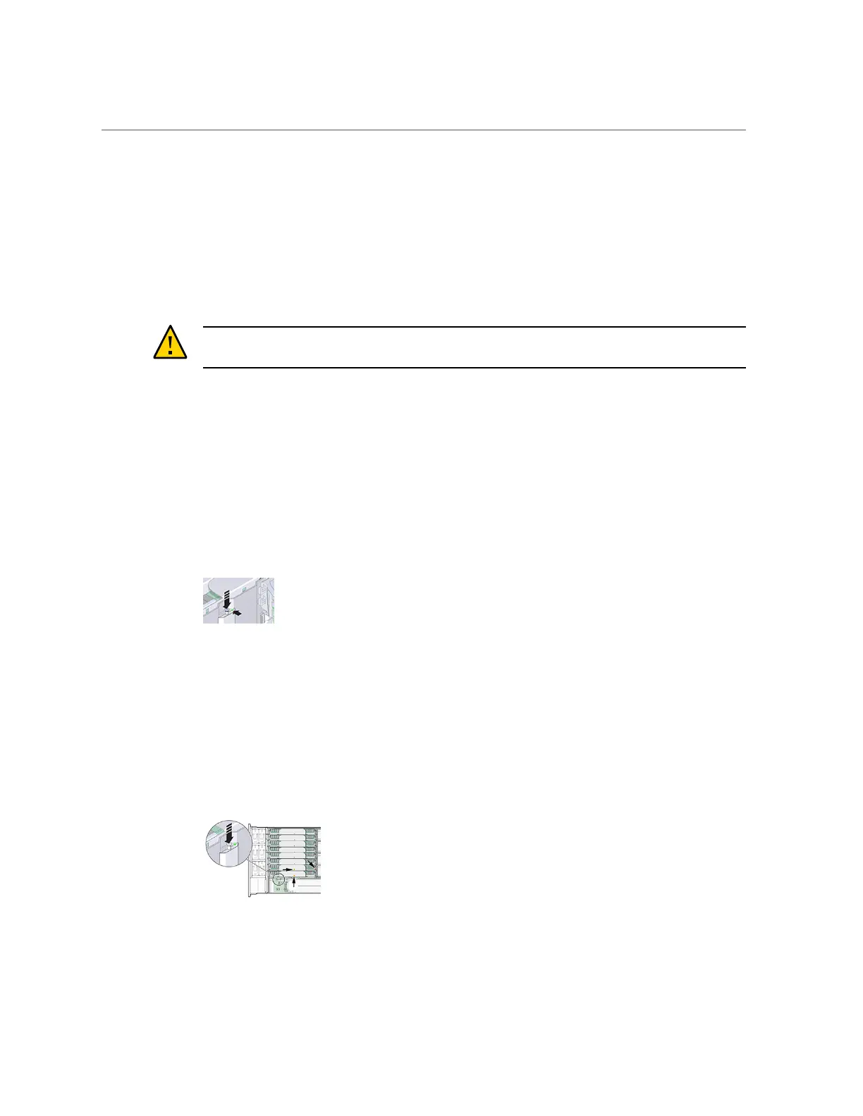
To locate the faulted component, first press and hold the Fault Remind button to
verify that the remind circuitry is usable. The Fault Remind button is located on
the divider between cooling zone 1 and cooling zone 2. The Power LED, next to
the button, is green when the remind circuitry is usable.
■
If a memory riser card has failed, see “Replacing a ZS4-4 Memory Riser
Card” on page 64 for removal and installation instructions.
■
If a DIMM has failed, see “Replacing a ZS4-4 DIMM” on page 62 for removal and
installation instructions.
■
If a CPU has failed, the LEDs for both memory riser cards associated with the failed CPU
turn on. The following example, shows the Fault indicators for memory riser cards, P0/MR0
and P0/MR1 are lit, as is the Fault indicator for CPU, P0.
Servicing the ZS4-4 Controller 61

 Loading...


