0
OPERATING INSTRUCTIONS
9
Volts Cord length Amps Gauge needed Amps Gauge needed
115/120V 25 ft 0 - 6 18 10 - 12 16
6 - 10 18 12 - 16 14
115/120V 50 ft 0 - 6 18 10 - 12 16
6 - 10 18 12 - 16 14
115/120V 100 ft 0 - 6 16 10 - 12 14
6 - 10 14 12 - 16 not recommended
115/120V 150 ft 0 - 6 14 10 - 12 12
6 - 10 12 12 - 16 not recommended
220/240V 50 ft 0 - 6 16 10 - 12 16
6 - 10 16 12 - 16 12
220/240V 100 ft 0 - 6 16 10 - 12 16
6 - 10 16 12 - 16 12
220/240V 200 ft 0 - 6 16 10 - 12 14
6 - 10 14 12 - 16 not recommended
220/240V 300 ft 0 - 6 14 10 - 12 12
6 - 10 12 12 - 16 not recommended
Table 1
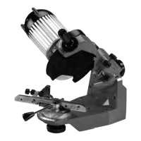
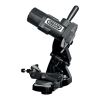
Inspecting the Chain
Always inspect an incoming cutting chain and review any
problems with owner or user. Always check for proper
installation of tie straps and/or reversed drive links.
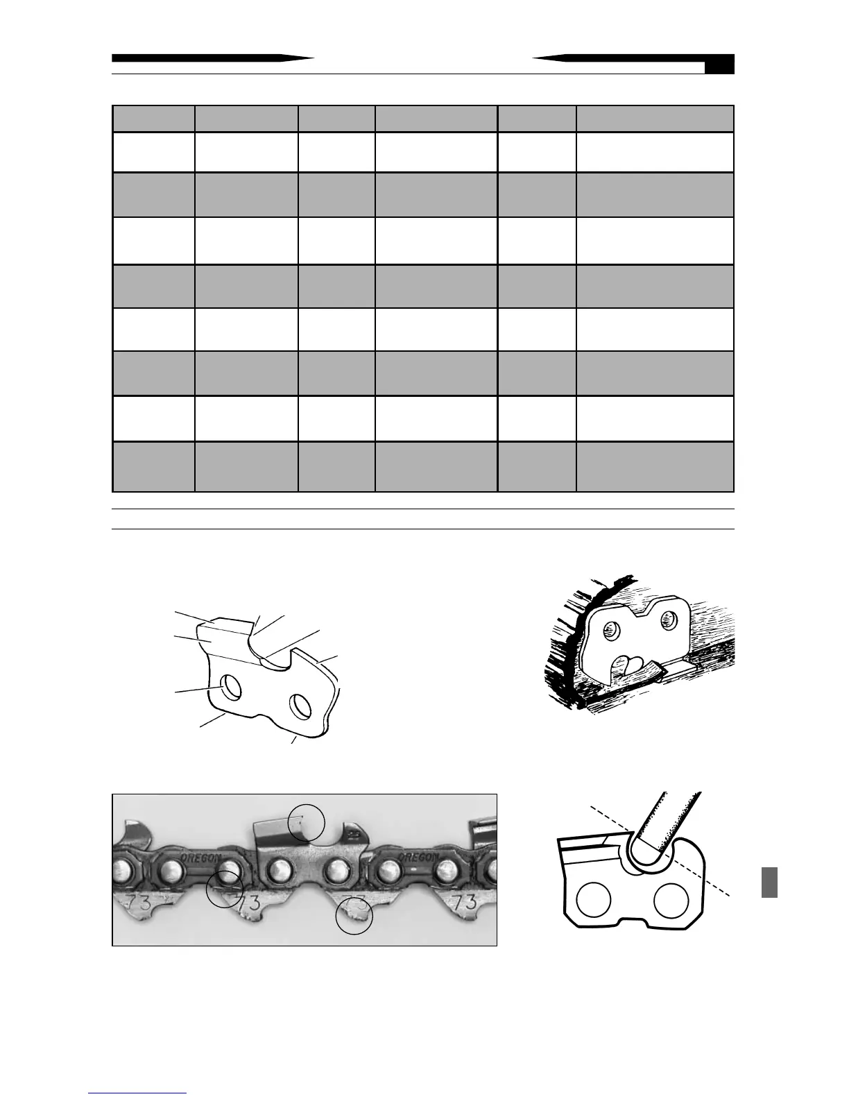
How a Cutter Works
A. Depth gauge
(controls bite of
the cutter).
B. Working corner
(slices the cross
grain – does most
the work).
C. Top plate edge (lifts out chips after cross grain
has been cut).
D. + E. Heel and toe (support cutter while working).
Top Plate
Side Plate
Rivet Hole
D. Heel
E. Toe
C. Top Plate
Edge
B. Working Corner
A. Depth
Gauge
Parts of a Cutter
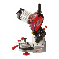
Gullet
Note: For proper side plate angle,
do not grind the gullet deeper
than where the grinding wheels’
radius meets the flat of the wheel.
(see Illustration).
Grinding A Chain