i Series User Manual
4
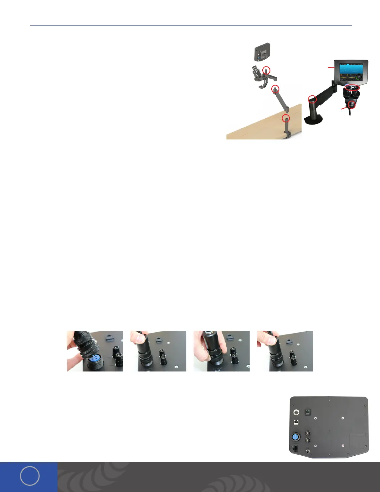
Microscope Arm Setup
1. Place the microscope extender arm into the arm base.
2. Place the microscope arm into the top of the extender arm.
3. Place the touch screen box into the slot on the microscope arm above
the microscope optics.
4. Loosen/tighten the allen on the top of the microscope extender arm
to adjust the spring pressure. Turn the allen counter clockwise if the
arm does not hold the microscope up. Turn the allen clockwise if the
arm does not allow the microscope to come down.
5. Ensure the RJ45 microscope cable is plugged into the RJ45 port on the
light ring (below the microscope optics).
6. Plug the other end of the microscope cable into the RJ45 “Shutter”
port on the back of the touch screen box. *Orion RJ45 ports are not compatible with any other RJ45 ports. Connecting
them to other devices may damage the welder and/or the other devices.
7. Install the rubber eyepiece covers onto the optics.
8. Loosen the bolt in front of the microscope mount to move the microscope head left and right.
*When adjusting the spring pressure as described in step 4, be sure the arm is parallel to the table as seen here.
Welder Connection Setup
CONNECT THE WELDING STYLUS TO THE BACK OF THE TOUCH SCREEN BOX
e welding stylus requires the most attention during setup. Since argon gas will flow through the stylus, a tight fit between
the power supply and the stylus is critical. is will insure that no oxygen is entrained into the weld. To accomplish this,
follow the steps below.
1. Position the end of the stylus so that the notch is facing down.
2. Push the stylus into the stylus connector port on the back of the touch screen box.
3. Turn the outside layer of the stylus connector clockwise so it screws onto the stylus connector port.
4. Continue to turn the outside layer of the stylus connector clockwise until it stops.
5. Now push in on the stylus connector, (you will feel it move in a couple centimeters). en turn the outside layer of the
stylus connector clockwise until it stops.
6. Repeat steps 2-5 until you feel the stylus connector bottom out, and you can no longer screw the stylus connector
clockwise. is will insure that the stylus connector is firmly seated.
CONNECT THE REMAINING CABLES TO THE BACK OF THE TOUCH SCREEN BOX
1. Place an alligator clip into the positive port on the back of the touch screen box. *Remember
to attach the alligator clip to the work-piece before welding.
2. Plug the foot pedal into the “trigger” port on the back of the touch screen box.
3. Verify that the RJ45 cable is securely fastened in the RJ45 port.
4. Insert the 1/4” gas tube firmly into the “Gas” port. *It may wiggle when connected, but
should not come out if pulled on.
8.
5.
4.
7.
6.
1.
2.
3.
 Loading...