10
UM0972080 A 03
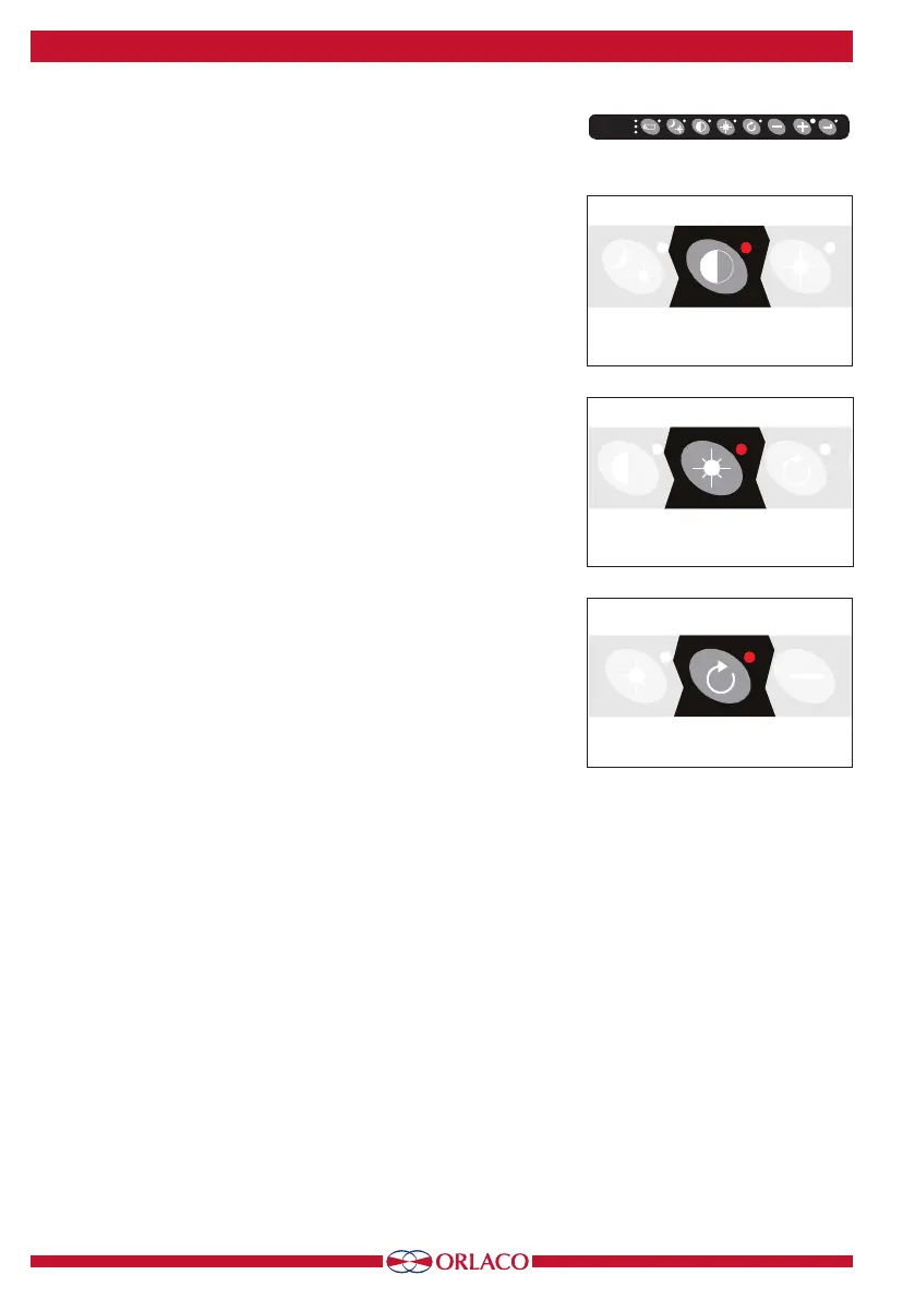
3.3. Button 3, setting the contrast
Press the contrast button (3) once to enable the setting mode (see
Figure 7). Use the minus and plus buttons to set the required contrast.
This setting must be set separately for each camera.
3.4. Button 4, setting the brightness
Press the brightness button (4) once to enable the setting mode (see
Figure 8). Set the required brightness using the minus and plus buttons.
This setting must be set separately for each camera.
3.5. Buttons 3 and 4, setting color saturation
Press the contrast (3) and brightness (4) buttons simultaneously to en-
able the setting mode.
Set the required color saturation using the minus and plus buttons. This
setting must be set separately for each camera.
3.6. Locking buttons 2, 3 and 4
These buttons can be locked in the service menu (section 4.3.3. key-
board, see page 16).
3.7. Button 5, option button
• Single scan sequence
If the option button (5) is pressed and a CCC is selected (see camera
settings on page 12), then the LEDD Monitor generates a single scan
(not continuous) of multiple connected cameras in a sequence (using
the set time interval. The scan time must only be set if the main scan
is started and then stopped again). See page 18, scanning.
• Connection with an AFI/AFZoom camera
This option enables the zoom function (indicated by the illuminated
button). The zoom factor can be changed using the plus and minus
buttons.
• Connection with a TIC camera
Zoom factors for a TIC camera are: 1x (standard display), 2x and 4x.
When zooming out to 1x, the pan/tilt function is set at the starting
point.
• Connection with a PTZ camera
If pan/tilt is enabled and the option button (button 5) is pressed
several times, then the ZOOM, PAN, TILT sequence is run through
(see Figure 10). The minus and plus buttons are used to activate the
ZOOM, PAN or TILT movement (PAN and TILT for a TIC camera only
work if the digital zoom is 2x or 4x).
The TIC camera video standard and spot meter settings are only ac-
cessible via the camera menus. There are no keys for direct access to
these settings.
See page 12, section 4: service menu, camera settings.
3. Keyboard
Figure 8
Figure 9
Figure 7
Button 1
Button 1
Button 1
Button 2
Button 3
Button 4
Button 5
Buttons 6 + 7
Buttons 5,6,7,8
Buttons 6 + 7
Button 1
Button 1
Button 1
Button 2
Button 3
Button 4
Button 5
Buttons 6 + 7
Buttons 5,6,7,8
Buttons 6 + 7
Button 1
Button 1
Button 1
Button 2
Button 3
Button 4
Button 5
Buttons 6 + 7
Buttons 5,6,7,8
Buttons 6 + 7
Buttons 1 2 3 4 5 6 7 8
monitor are
closer than
C3
C2
C1