20
UM0972080 A 03
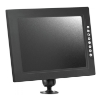
5.2. Camera settings (see Figure 39)
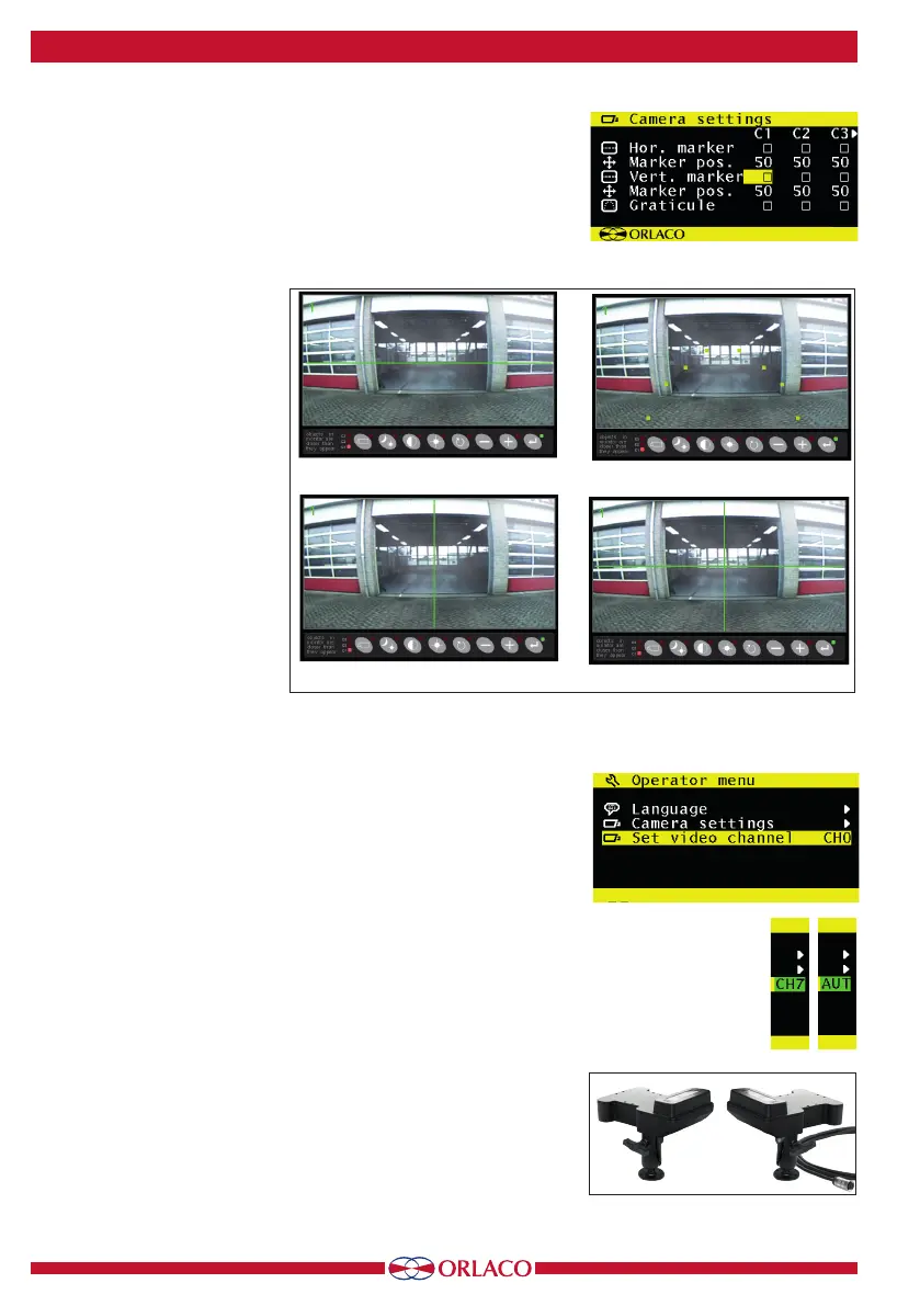
Horizontal line mark
Enable this option to show a reference line. The reference line is
displayed as a horizontal green line. See Figure 40.
Line position
Adjusts the vertical height of the reference line. 0 corresponds to the
top edge of the monitor and 100
to the bottom edge.
Vertical line mark
Enable this option to show a
reference line. The reference line
is displayed as a vertical green
line. This option is not available
on all RLED/LEDD models. See
Figure 40.
Line position
Adjusts the vertical position of
the reference line. This can be
set between 38 and 63. The left
and right sides swap position
depending on the settings of the
camera mirror-image function.
Graticule
This option shows a graticule for
a rearview camera on the moni-
tor. See Figure 40.
5.3. Video channel settings
See Figure 41.
This option sets the video channel for the Orlaco Spectrum Scanner
(see Figure 42).
The following options are available:
CH0 = channel 0 to CH7 = channel 7
AUT = automatic
See the Spectrum Scanner IM0973610 installation manual for des-
criptions of these channels.
Figure 39
Horizontal
Vertical
Horizontal and vertical
Graticule
Figure 40
Figure 41
Figure 42
5. Operator menu