12
UM0972080 A 03
Figure 13
Figure 16
Figure 14
Figure 15
4. Service menu
Buttons 1 2 3 4 5 6 7 8
Button 1
Button 1
Button 1
Button 2
Button 3
Button 4
Button 5
Buttons 6 + 7
Buttons 5,6,7,8
Buttons 6 + 7
Button 1
Button 1
Button 1
Button 2
Button 3
Button 4
Button 5
Buttons 6 + 7
Buttons 5,6,7,8
Buttons 6 + 7
4. Using the service menu
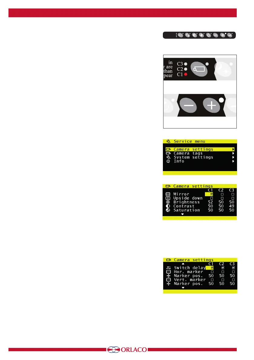
To open the service menu, simultaneously press the camera selection
button (1), the minus button (6) and the plus button (7) (see Figure 13).
The Monitor (see Figure 14) will appear. The following buttons are used
to navigate through the menus:
5 - Option/previous menu: Return to the previous menu
6 - Minus: Go to the next menu option
7 - Plus: Go to the previous menu option
8 - Enter: Select or enable the chosen option
4.1.
Camera settings
Select camera settings. Press enter to open the 'Camera settings' menu. Use
the minus (6) and plus (7) buttons to select which camera to configure. Then
confirm this selection by pressing the enter button (8). The yellow cursor is
now activated in the list of items. Use the minus (6) and plus (7) buttons to
select the item to adjust and then confirm this selection by pressing the enter
button. If the selection is an on/o switch, you can choose between on and
o. If the selection is a number, you can change the value using the minus (6)
and plus (7) buttons. Save the new settings by pressing the enter button (8).
4.1.1. Mirror
Enable this option to reverse the image (left/right).
4.1.2. Upside down
This option flips the image (upside down).
4.1.3. Brightness
The setting for the brightness of the monitor. For direct button operation:
Button 4.
4.1.4. Contrast
The setting for contrast on the monitor. For direct button operation:
Button 3.
4.1.5. Saturation
The color saturation setting for the camera image. For direct button
operation: Buttons 3+4.
4.1.6. Switch delay
Enable this option if the switchwire is controlled by an intermittent
signal (e.g. from an indicator light).
4.1.7. Horizontal marker
Enable this option to show a reference line. The reference line is dis-
played as a horizontal green line. See Figure 40 on page 19.
4.1.8. Marker position
Adjusts the vertical height of the reference line. 0 corresponds to the top
edge of the monitor and 100 to the bottom edge.
monitor are
closer than
C3
C2
C1
monitor are
closer than
C3
C2
C1