CableConnectionandPinout
TheRev7OS0canbeoperatedwithouttheuseofanInterfaceBox. FormoreinformationontheOuster
CablePinoutpleaserefertoDirect CableConnection and Pinout.
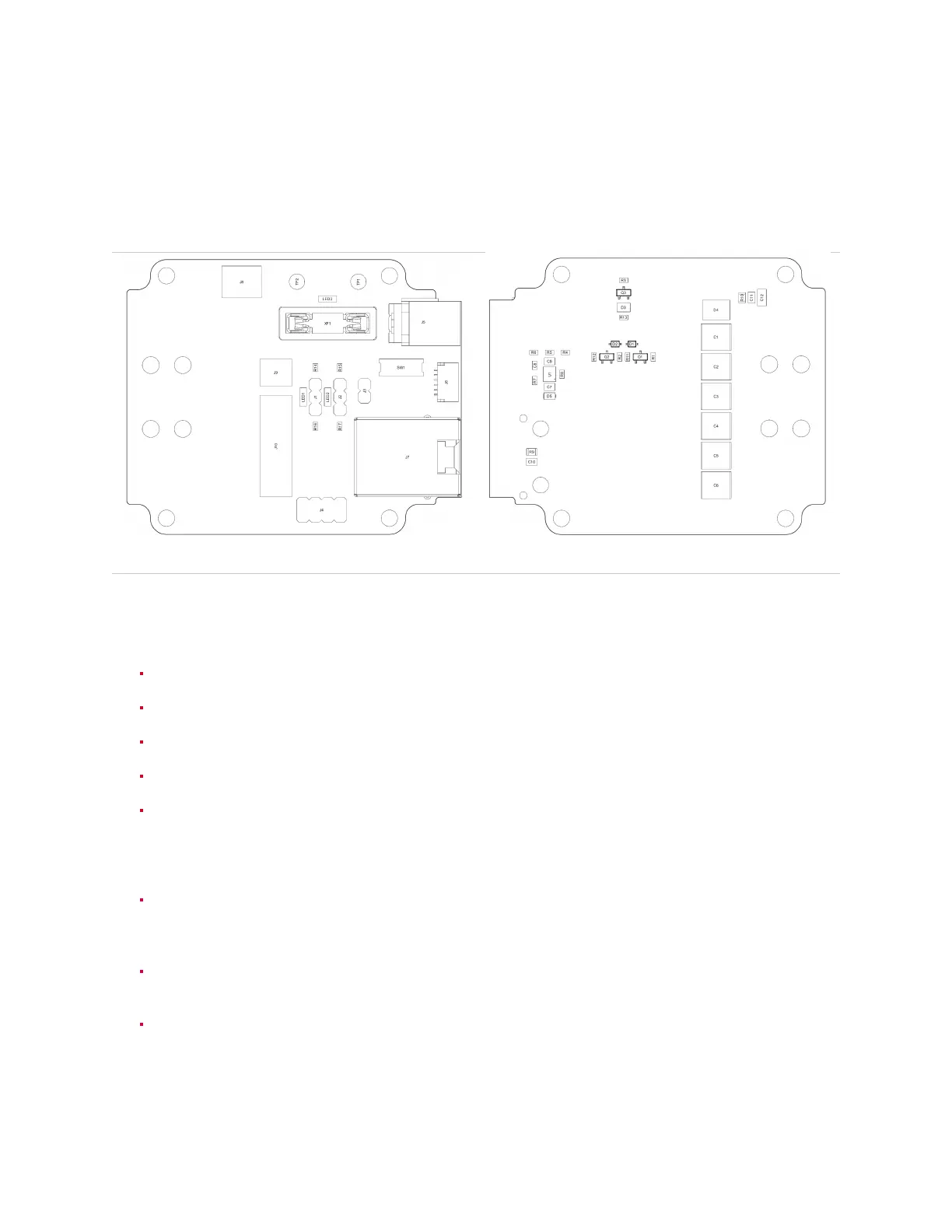
Table7.3: InterfaceBoxConnectionDiagram(PCBAPN-830-104249)
Fig.7.5: Frontpane
Fig.7.6: RearPane
Specification
GigabitethernetRJ45jack(1000BASE-T).
VINBarrelJack. Usewitha5.5mmODx2.5mmIDbarrelplug.
Userreplaceable5Afuse. UseonlyLittlefuse #0891005.
VINgreenLEDindicator.
OnboardbuckpowersupplygeneratingVCC_IO.VCC_IOsuppliestheonboardLEDsandpullups,
and is user accessible via headers J3 & J4. Switch SW1 is used to select the buck’s output
voltage. WARNINGS:Maxallowableuser consumption is 210mA. Ensurepowertothe Interface
BoxisdisconnectedwhenchangingbuckoutputvoltageviaSW1.
10kωpull-downs,3.3kωpull-upstoVCC_IO,andyellowLEDindicatorsforSYNC_PULSE_INand
MULTIPURPOSE_IO.Installajumperontherespectiveheader(J1orJ2)toenablethepull-down
orpull-up.
0.1” pitch, 4x2 pin header J4. GPS_TX (Pin 1) is only connected to connector J6; it is not con-
nectedtothesensor.
6-pinJSTSH/SRconnectorJ6. VCC_GPS(Pin2)isconnectedtoVCC_IObyinstallingajumper
onheaderJ3. GPS_TX(Pin6)isonlyconnectedtoheaderJ4;itisnotconnectedtothesensor.
27