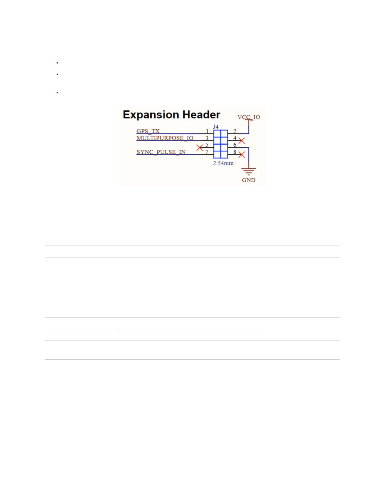
ConnectionusingthePinout
ConnectthePPSoutputfromyourGPStothesync_pulse_inpinoftheOusterInterfaceBox.
ConnecttheNMEAUARToutputfromyourGPStothemultipurpose_iopinoftheOusterInterface
Box.
ConnectthegroundoutputfromyourGPStotheGNDpinoftheOusterInterfaceBox.
Figure 8.2: HeaderPinout
BasedonthetypeofinterfaceboxbeingusedpleaserefertoeitherModularInterfaceBoxSchematic
Diagram orHighCurrentInterface Box(PCBA 830-104249) - Standard.
Table8.1: SYNC_PULSE_INInterfaceRequirements
Parameter MinVoltage MaxVoltage MinDriverCurrent
LOGICLOW -30V 2V N/A
LOGICHIGH 2.9V 30V 3mA @3.3V~5V, 5mA
at24Vandhigher
Table8.2: MULTIPURPOSE_IO-INPUTInterfaceRequirements
Parameter MinVoltage MaxVoltage MinDriverCurrent
LOGICLOW -30V 2V N/A
LOGICHIGH 2.9V 30V 3mA @3.3V~5V, 5mA
at24Vandhigher
35