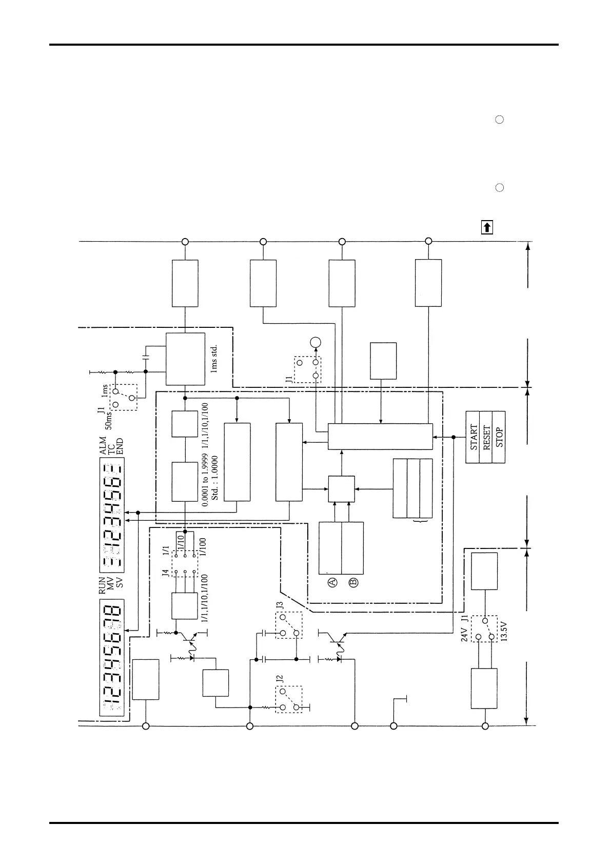
7. BLOCK DIAGRAM
LCD 2 Disp. (batch reading 8-digit) LCD 1 Disp. (batch setting 6-digit)
Power to generator
Flowrate signal
input
Remote control input
Power
1,3
4,5
9,10
21,22
11 to 16
2
17,18,19
20
6,7
24V
13.5V
START
RESET
STOP
85 to 264VDC
50/60Hz
Power to
generator
Wave-
shape
Regulated
Voltage
source
Power to
generator
Freq.
divide
Freq.
divide
One-shot
multivibrator
1ms or
50ms
Batching
microprocessor
6-digit
Batch counter
8-digit
Total counter
Scaler
Front-panel
control keys
Display boardPower board Output board
Non-contact
relay
Non-contact
relay
Relay
Relay
Output to external total counter
TC
Non-contact relay output
Form “a” contact
End-of-batch output
END
Non-contact relay output
Form “a” contact
Alarm output
ALM
Relay contact output
Form “a” contact
(missing pulse, overshoot,
param. error)
Valve control signals
SV, MV
Relay output
Form “c” contact, one set each
NOTES
Missing
pulse alarm
Overmeasure
alarm
Com-
pare
Batch setting
Initial setting
Final setting
6-digit
0 to 999 counts
0: No setting
Default: 80 counts
Toggle
switch
RUN ⇔ SET
RUN: Run mode
SET : Setup mode
Buzzer
Counter
About A
0 to 15 sec.
0: No alarm
Default: 10 sec.
About B
0 to 99 counts
0: No alarm
Std.: 10 counts