E-215-7-E
25
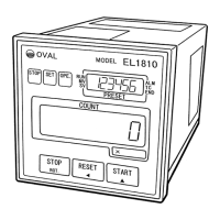
Fig. 9.5
Separate.
Output board
Power supply board
Rear panel
Power supply board
terminal block
Fig. 9.6
Output board
Shorting strip
➂
Extract the power supply board from the terminal
block on the rear panel.
➃
Make sure of a shorting strip which may possibly
exist on the terminal block of rear panel before
extracting the output board.
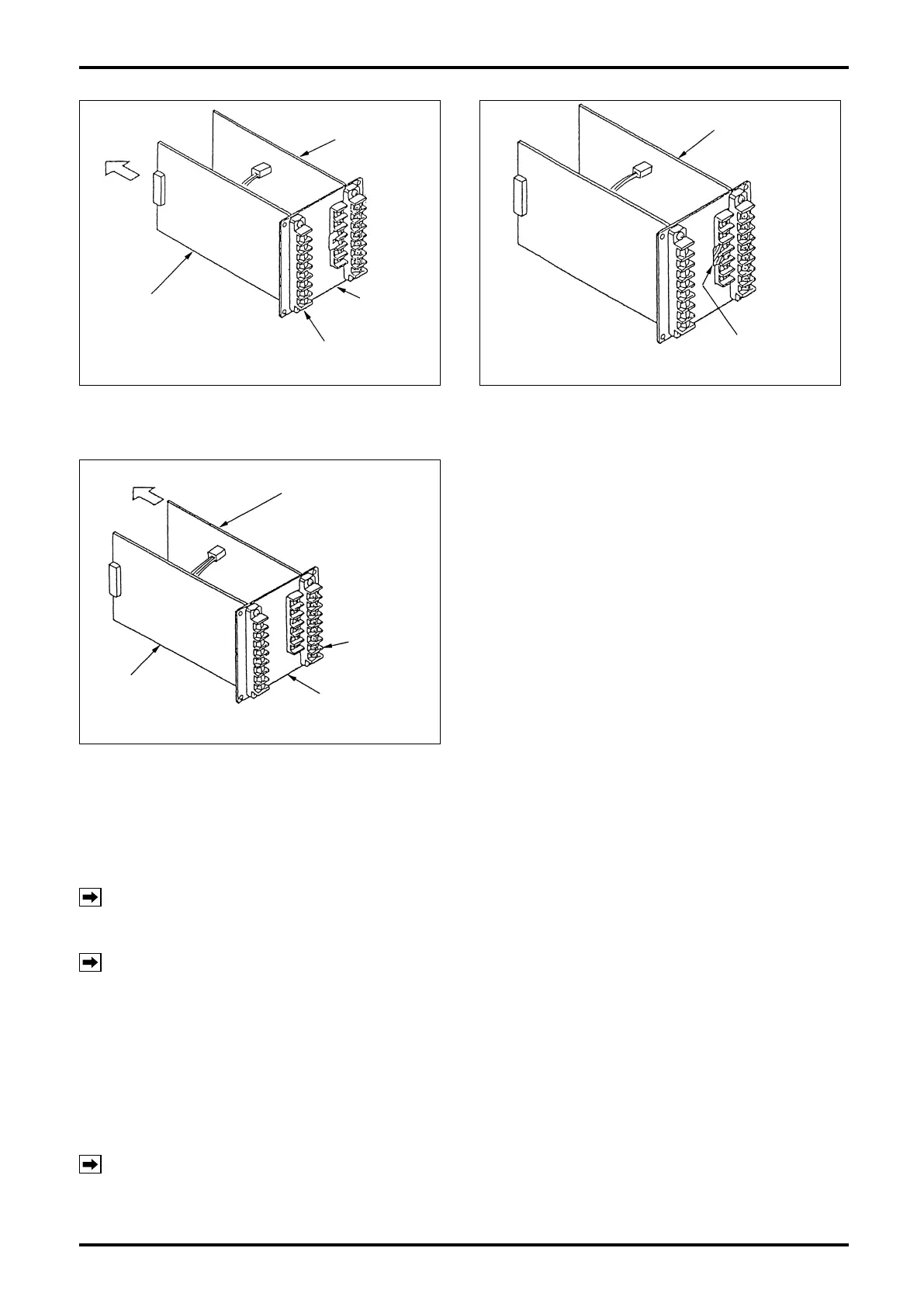
Fig. 9.7
Separate.
Output board
Output board
terminal block
Rear Panel
Power supply board
➄
If a shorting strip exists, remove it before
extracting the output board from the terminal
block of rear panel.
9.4 Assembling the Internal Assembly
9.4.1 Installing the Power Supply Board and Output Board
NOTE:
If a shorting strip is attached to the terminal block of the output board, remove it before
assembly.
➀
Install the output board and power supply board into the terminal block.
NOTE: Installation is correct if the power supply board and output board face each other with their
component parts.
➁
Install the power supply board and output board into the groove of top and bottom frames until the rear
panel of terminal blocks comes in contact with the frames.
9.4.2 Installing the Front Panel
In the state described in the previous section, install the front panel in place.
➀
With the two boards installed on the top and bottom frames, press the rear panel to connect CN1 and
CN2 of the display board with their mating connectors.
NOTES: 1. Misplaced board cannot be installed properly.
2. Take your time to ensure correct engagement of the right and left connectors.
➁
Upon completion of front panel attachment, install four long screws from the side of terminal block.