E-215-7-E
28
10. TROUBLESHOOTING
10.1 Inspection Items
NOTE: If trouble is found to be internal, isolate the problem according to the table below and seek our
service.
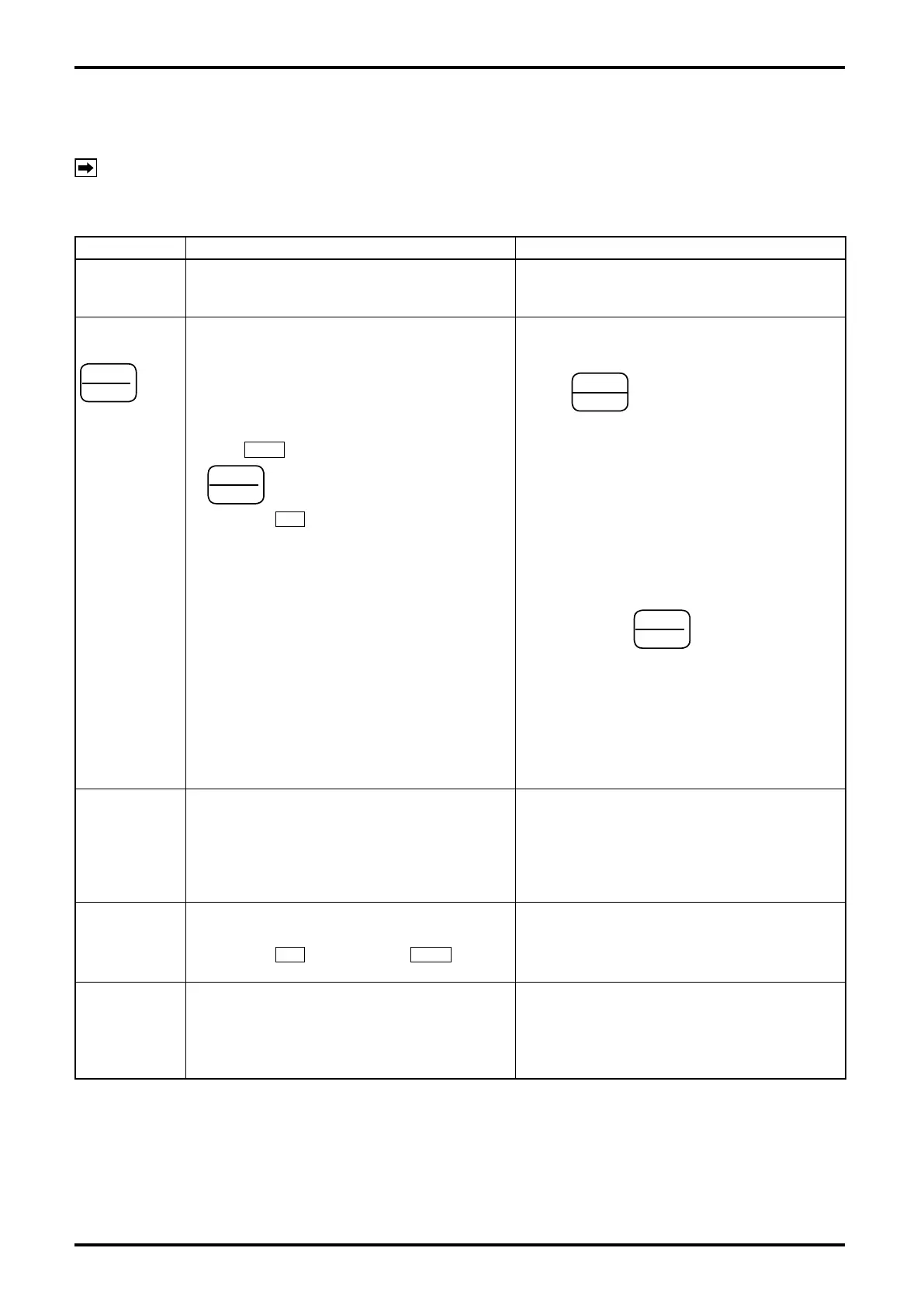
Table10.1
Symptom Inspect Possible causes
Display is dead. 1. Inspect fuse.
2. Check supply voltage.
AC version 85 to 264VAC
1. Fuse is blown. (
⇒
See page 29.)
2. Supply voltage is incorrect.
3. A fault in the controller.
Valve fails to
respond to
START
▲
key
depression.
1. Check to see if terminals 19 and 20 (remote
control input Stop, From “b” contact) on the
terminal block are shorted.
1. Unless terminal 19 and 20 (remote control input
STOP) on the terminal block are shorted by a
switch having a Form “b” contact or a shorting
strip,
STOP
ROT.
key always remains depressed,
leaving that key inoperative.
2. Dose
OPE
come on in response to
START
▲
key depression?
Does LCD
SV come on at the same time?
2. A fault in the controller.
3. Do valve control signals SV and MV actuate
property?
SV : 11, 12, 13 on the terminal block
MV: 14, 15, 16 on the terminal block
3. Valve control signal output relays are at fault.
4. Isn’t the batch set to 0?
4. At touch of key
START
▲
an end-of-batch signal
is produced at once.
5. Are valve control signal wiring and supply voltage
correct?
5. Valve control output lines are incorrectly wired or
an open in the cable.
6. Are valve operating and control pressure settings
correct?
6. Valve operating and control pressure settings are
incorrect.
7. Has the batch process been reset?
(Alarm reset, end-of-batch output reset, etc.)
7. Reset the batch process.
Valve operates
but the total
counter fails to
count.
1. Is a owrate signal coming in from the owmeter? 1. Incorrect wiring or an open in the cable.
A fault in the owmeter itself or in the pulse
generator.
2. Is the incoming owrate signal within the
acceptable frequency range of response?
2. Outside the acceptable frequency range of
response. (The microprocessor accepts pulses
up to 200Hz.)
Fails to perform
batch operation
at the setpoint.
1. Do valve control signals SV and MV actuate
when the target batch quantity is reached?
1. Valve control signal output relay is at fault.
2. Does LCD
SV go out and LCD END come on
when the target batch quantity is reached?
2. A fault in the controller.
Remote control
is inoperative.
1. Is it possible to control with front panel control
keys?
1. Remote control signals are incorrect if
controllable with front panel control keys.
2. Is remote control circuitry wired correctly? 2. Remote control circuitry is wired incorrectly, or
the cable has an open.
Or a fault in the controller.