E-215-7-E
8
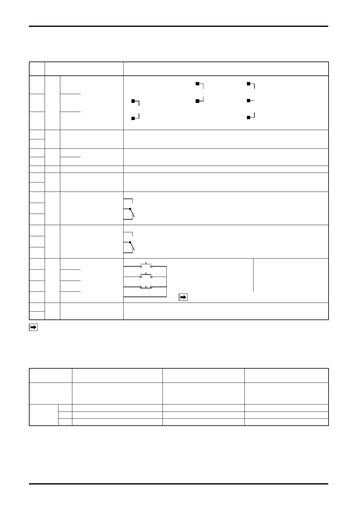
5.4 Identifying the External Connection Terminals
Table 5.1
Term.
No.
Label Required Conditions for Connections and Specications
1
Flow Signal Input
SUP.
FLOW SIG
INPUT
Current pulse
[PA14, 15, 25,
NPG60A (E)]
Contact-closure pulse
Open collector pulse
2-wire voltage pulse
(PG20, Coriolis meter)
3-wire open collector
3-wire voltage pulse
[PG30, NPG60A (F),
60 (E3), FLOWPET- EG]
2 SIG.
3 COM.
4
Output to
External
Totalizer
TOTAL COUNT OUTPUT
Non-contact relay output, a set of Form “a” contact Capacity: 250V AC/DC 0.15A
Output pulse width: 1ms (standard) or 50ms
5
6
Power
L1 (+)
POWER
SUPPLY
85 to 264VAC 50/60Hz
7 L2 (–)
8 GND Ground terminal
9
End-of-
Batch
Output
BATCH END OUTPUT Non-contact relay output, a set of Form “a” contact Capacity: 250V AC/DC 0.15A
10
11
Valve Control
Signal
VALVE OPERATION
SIGNAL (SV)
Partial-flow signal (SV): Initial open signal
Relay
contact output, a set of Form “c” contact
Capacity: 250VAC, 1A
a
c
b
12
13
14
Valve Control
Signal
VALVE OPERATION
SIGNAL (MV)
a
c
b
Upper-limit flow signal (MV): Full-open signal
Relay contact output, a set of Form “c” contact Capacity: 250VAC, 1A
15
16
17
Remote Control
Input
START
REMOTE
CONTROL
INPUT
START: Form “a” contact
RESET: Form “a” contact
STOP: Form “b” contact
Contact current:
10mA max. at 15VDC
Signal width:
Instantaneous signal
※:
1 sec.
18
RESET
19
STOP
20 COM.
NOTE: Short STOP when not in use.
21
Alarm
Output
ALARM OUTPUT
An output on detection of missing pulses, overmeasurement, parameter error Relay
contact output, Form “a” output Capacity: 250V AC, 1A
22
NOTE
※
: Provide at least 2 seconds between individual signals (see page 10).
5.5 Flowrate Input and their Terminals
Table 5.2
Signal Type
Contact-closure Pulse, 2-wire
Voltage Pulse, Open Collector Pulse
Current pulse
3-wire open collector pulse
3-wire voltage pulse
Generator PG20, Coriolis owmeter PA 14, 15, 25, NPG60A (E)
PG30, NPG60A (F),
NPG60A (E3),
FLOWPET-EG
Terminals
1
—— ○
+
○
SUP.
2
○
+
○
–
○
SIG.
3
○
–
—— ○
COM. (0V)
○
: Terminals in use