E-215-7-E
6
4. INSTALLATION
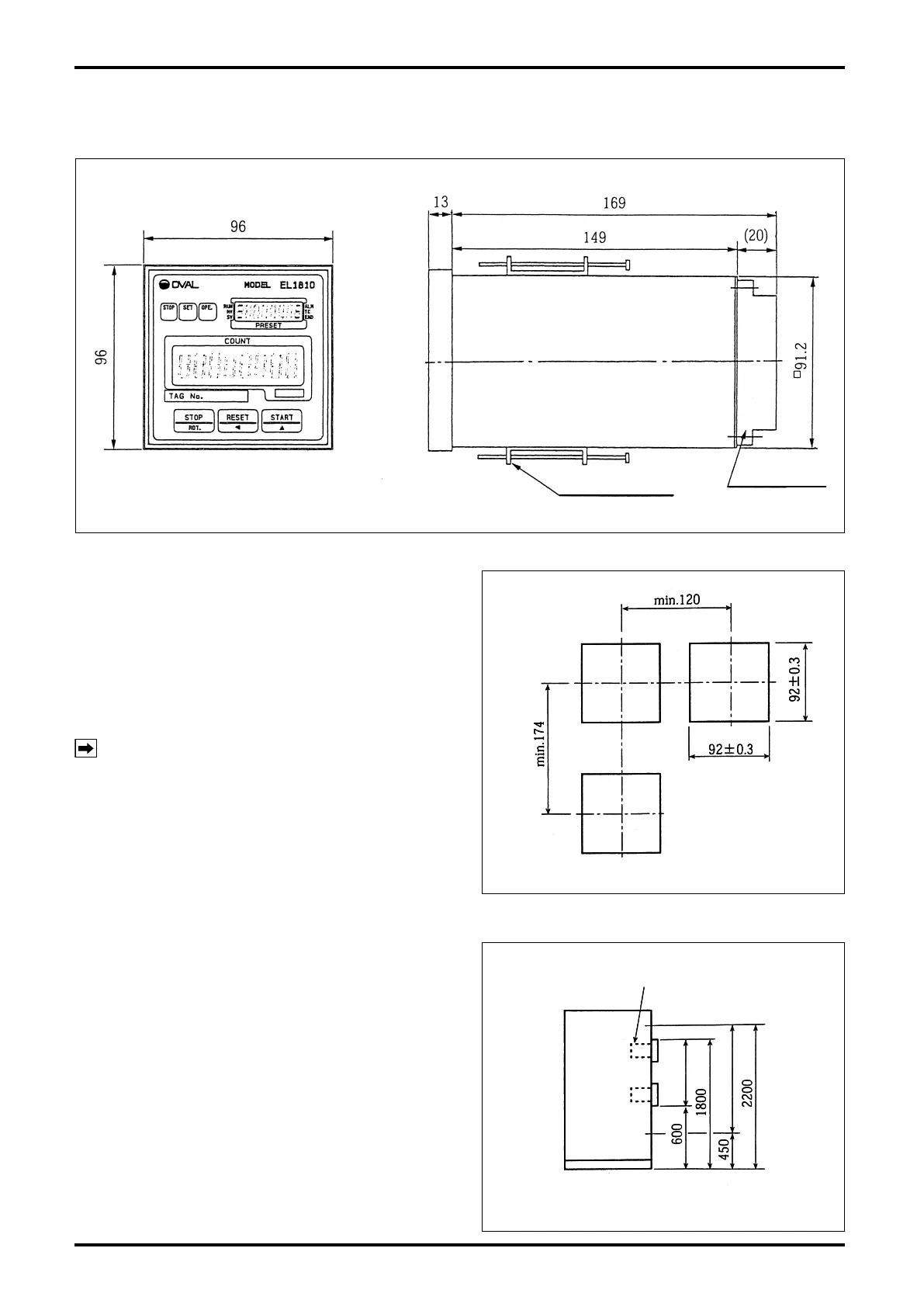
4.1 Outline Dimensions
Terminal block
Panel-mount fitting
All dimensions in millimeters
Fig. 4.1 Outline Dimensions
4.2 Installation
4.2.1 Installation Location (Indoor only)
Select an installation site where:
(1) Mechanical vibration, shock and corrosive gases
least exist.
(2) The air is dry and at around room temperature
and stable.
(3) A place where is not exposed to the direct
sunlight.
NOTE: Although the manufacturer guarantees
stated performance at ambient temperatures
from –10 to 50°C, it is recommended that
the instrument be placed in service at room
temperature.
(4) Provide a sufficient working space behind the
instrument – at least 50 centimeters from the
back panel of the instrument to facilitate wiring
and servicing.
4.2.2 Panel
(1)
Use a rigid steel sheet with a minimum thickness of
1.6 millimeters. Recommended thickness is 3.2mm.
(2) If it is required to mount the computers side by
side, dimensions in Fig. 4.2 are suggested.
(3)
Recommended mounting height is given in Fig. 4.3.
4.2.3 Installation
(1) Insert the instrument through the opening in the
mounting panel.
(2) Hook the enclosure hold-down ttings to the slots
in the rear of the enclosure and, conrming that
the instrument is positioned on a level plane,
secure the instrument to the panel with panel-
mount ttings (Fig. 4.1).
All dimensions in millimeters
Fig. 4.2 Panel Cut
All dimensions in millimeters
Fig. 4.2 Panel Cut
All dimensions in millimeters
Batch controller
Fig. 4.3 Mounting Height
All dimensions in millimeters
Batch controller
Fig. 4.3 Mounting Height