E-215-7-E
27
9.6 Setup on the Output Board
NOTE: Remove the output board before conguring the board.
CAUTION: Do not forget to remove power to the instrument before you work.
9.6.1 Buzzer Sound Setup on Alarm (missing pulse, overmeasurement, and parameter
error) Detection
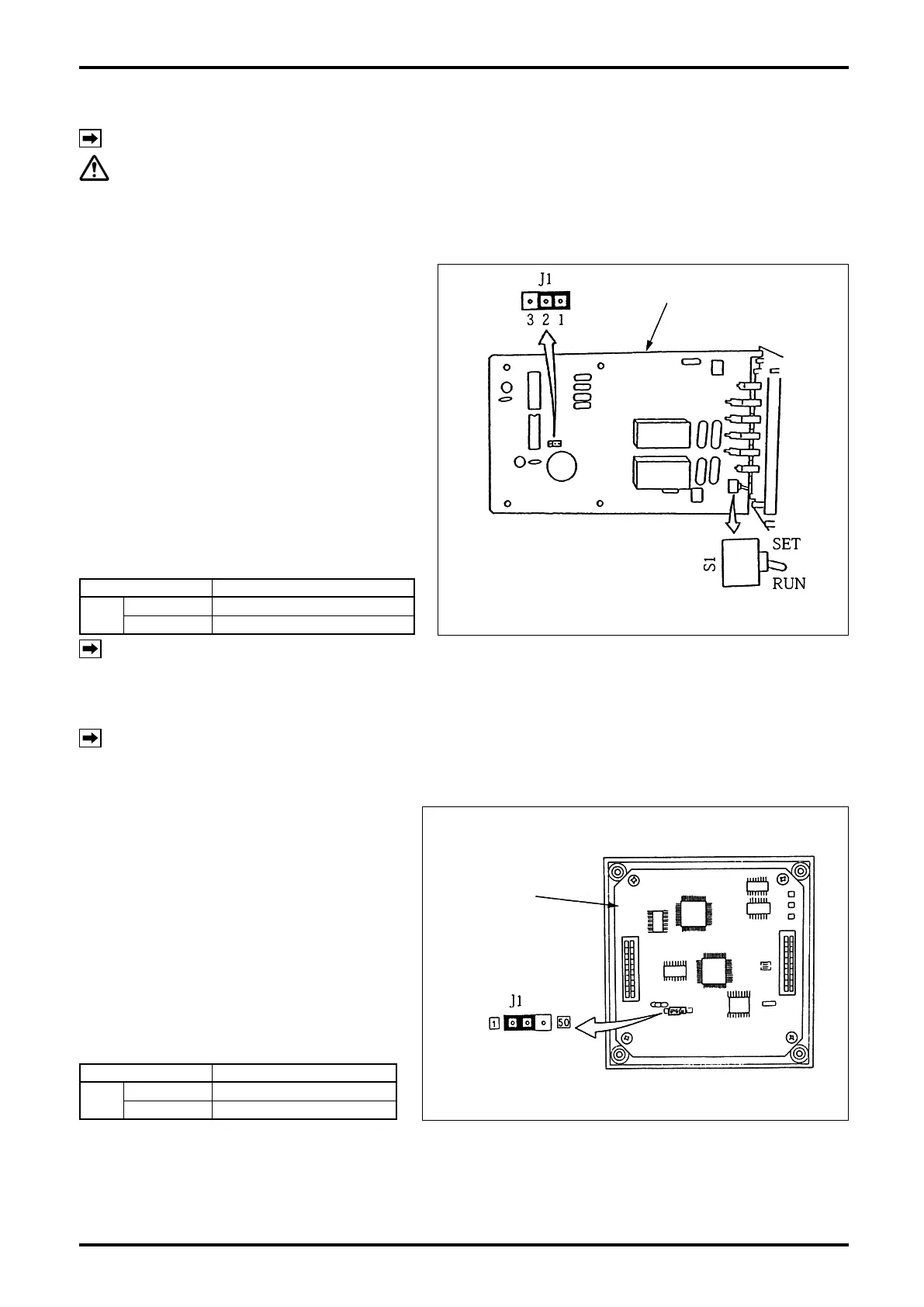
Buzzer sound upon alarm detection (missing
pulse, overmeasurement, and parameter error)
is set up by selecting the position of jumper J1.
Set the jumper J1 on the output board in the
position desired, referring to Table 9.3.
J1 in Fig. 9.10 shows the standard (1-2)
position.
Table 9.3
Jumper Description
J1
1 – 2
Buzzer sound (default)
2 – 3 Buzzer disabled
NOTE: As for toggle switch S1 in Fig .9.10, refer to Sec. 9.1.2 on page 22.
9.7 Reconfiguration on the Display Board
NOTE: Work with the display board LCD (front panel) removed.
9.7.1 Total Counter Output Pulse Width Selection
Jumper (J1) located on the display board
selects the total counter output pulse width.
Set the position of jumper J1 on the display
board shown in the sketch at right to choose
between two pulse width positions according
to Table 9.4.
Table 9.4
Jumper Description
J1
1 side
Pulse width 1ms (default)
50 side Pulse width 50ms
Output board
Fig. 9.10 Output board (an example of J1 setting)
Output board
Fig. 9.10 Output board (an example of J1 setting)
Display board
Fig. 9.11 Display Board
Display board
Fig. 9.11 Display Board