E-215-7-E
22
9.1.2 Setup Mode
CAUTION: Be sure to turn off power before you work.
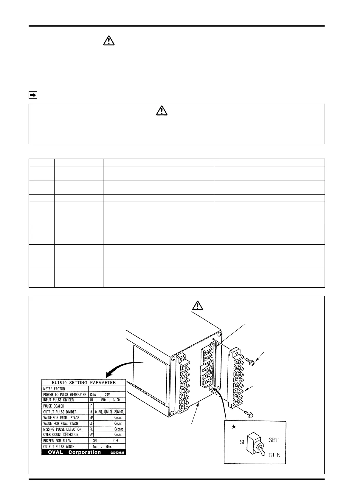
Remove the terminal block holding terminals Nos. 9 through 16 and place toggle switch S1 at
★
mark in
Fig. 9.1 in the “SET”.
Turning power on will bring the controller into the setup and the entire LCD will icker.
In this setup mode, the following parameters can be congured. [Factory default settings appear on the
setup label attached to the side of the controller. See Fig. 9.1.]
NOTE: The controller is shipped at default settings unless otherwise specied by the customer.
CAUTION
During a batch process, in an interrupted or completed state of operation, or in an alarmed
condition, a transfer to the setup mode is disabled. Cancel the batch process or clear the
alarmed event by pressing RESET button first before you retry.
Table 9.1
Symbol Item Setup range Default setting
Total reading reset
(gure adjustment)
00000000 to 99999999
——
F Scale Factor 0.0001 to 1.9999
Meter factor the meter used
Default: 1.0000 or customer’s specication
d Frequency division 0: 1/1, 1: 1/10, 2: 1/100 Default:0 (1/1) or customer’s specication
oP Initial setting
0 to 999 counts
(Set to 0: Two-stage open disabled;
SV and MV open simultaneously.)
Default: 80
or customer’s specication
cL
Final setting
0 to 999 counts
(Set to 0: Two-stage close disabled;
SV and MV close simultaneously.)
Default: 80
or customer’s specication
PL
Missing pulse
setting
0 to15sec
(Set to 0: Missing pulse alarm
detection disabled)
Default: 10
or customer’s specication
oV Overshoot setting
0 to 99 counts
(Set to 0: Overmeasurement alarm
detection disabled)
Default: 10
or customer’s specication
Output board
Take off two setscrews
securing the terminal
block and separate the
terminal block forward.
Terminal block
(Terminals 9 thru 16)
Rear of Batch Controller
Parameter settings label
Fig. 9.1
Toggle Switch
CAUTION
Be sure to turn off power before you work.