EasyManua.ls Logo

OXIGRAF O2iM User Manual

OXIGRAF O2iM
27 pages
To Next Page IconTo Next Page
Page #1 background imageLoading...
Page #1 background image
February 13, 2007 08-0427-B0, Manual, O2iM.doc Page 1
INSTRUCTION MANUAL
OXIGRAF O2iM
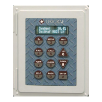
NEMA 4X Oxygen Deficiency Monitor
1170 TERRA BELLA AVENUE MOUNTAIN VIEW, CA 94043
TEL (650) 237-0155 FAX (650) 237-0159
oxigraf@oxigraf.com http://www.oxigraf.com

Table of Contents

Questions and Answers:

OXIGRAF O2iM Specifications

General IconGeneral
BrandOXIGRAF
ModelO2iM
CategoryMonitor
LanguageEnglish

Summary

Warnings, Cautions, and Notes

Introduction to the O2iM Analyzer

Product Description

Details the features and components of the O2iM oxygen deficiency monitor.

Options, Accessories, and Specifications

Lists optional configurations, available accessories, and initial technical specifications of the O2iM analyzer.

Detailed Specifications

Covers performance, electrical, and mechanical specifications, including diagrams.

Getting Started with O2iM

Analyzer Installation and Interfaces

Covers mounting, power connection, and basic interface setup for the O2iM analyzer.

Analog Output and Relay Contacts

Details the 4-20 mA analog output and the functionality of the relay contacts for alarms and status.

Alarm Relay, Horn, and Light

Explains the alarm relay activation, and the connection and function of the horn and strobe light.

Gas and Calibration Connections

Describes sample gas connection methods and the port for calibration gas input.

Operation of the O2iM Analyzer

User Interface and Power-Up

Explains the user interface, keypad, display, and the analyzer's power-up sequence.

Operational Modes Overview

Details the various operational modes like Run, Setup, Calibration, Test, and Help.

Calibration Procedures

Details the processes for setting up calibration points and the calibration sequence.

Gas Sampling and Alarm Status

Explains gas sampling controls and how to view the status of alarm relays.

Test Mode, Help, and Manual Calibration

Describes test modes, help functions, and the initial steps for manual calibration.

Autocalibration

Details the automatic calibration process, including setup and triggering conditions.

Autocal Input Source

Explains how to connect calibration gas sources, both pressurized and non-pressurized.

Configuration Parameters

O2 Filter and Measurement Settings

Sets O2 filter response, measurement range, and mode (XC/LN).

Multipoint and Scan Settings

Configures the number of channels and sampling time for multipoint operation.

Calibration Configuration Parameters

Sets low/high calibration gas values, autocal period, valve delay, and mode.

Output Setpoints and Flow Control

Defines 4-20mA output setpoints, flow setpoint, and pump state for operation.

Alarm and Relay Settings

Configures O2 and flow alarm thresholds, relay latch/flash/failsafe modes, and exclusive mode.

Relay Allocation and Horn/Strobe Mode

Defines relay allocation for channels or global status, and configures horn/strobe activation conditions.

Alarm Delay and Acknowledge Settings

Sets the delay time for recognizing alarms and the time for acknowledging them.

Dwell, Beep, and Keypad Lock Settings

Configures mode dwell time, keypad beep volume, and keypad lock settings.

Service and Support

Troubleshooting Guide

Lists common problems, their causes, and solutions with references.

Warranty and Return Procedure

Outlines the warranty terms and the procedure for returning the analyzer for service.

Appendix A – Menu Structure

Appendix B – Terminal Board Diagrams