Oxigraf O2iM NEMA 4X Oxygen Analyzer
February 13, 2007 08-0427-B0, Manual, O2iM.doc Page 3
Table of Contents
1. Warnings, Cautions and Notes............................................................................................................. 5
2. Introduction ......................................................................................................................................... 6
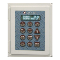
2.1 Product Description ...................................................................................................................6
2.2 Options.......................................................................................................................................7
2.3 Accessories ................................................................................................................................7
2.4 Specifications.............................................................................................................................7
2.4.1 Performance Conditions.....................................................................................................7
2.4.2 Performance Specifications................................................................................................8
2.4.3 Electrical Specifications.....................................................................................................8
2.4.4 Mechanical Specifications .................................................................................................8
3. Getting Started..................................................................................................................................... 9
3.1 Analyzer Installation..................................................................................................................9
3.1.1 Mounting the Analyzer ......................................................................................................9
3.1.2 Power .................................................................................................................................9
3.1.3 RS-232 Interface ................................................................................................................9
3.1.4 RS-485 Interface ................................................................................................................9
3.1.5 4 – 20 mA Analog Output................................................................................................10
3.1.6 Relay Contacts .................................................................................................................10
3.1.7 Alarm Relay .....................................................................................................................11
3.1.8 Horn and Light.................................................................................................................12
3.1.9 Gas Sample Connection...................................................................................................12
3.1.10 Cal Gas Connection .........................................................................................................12
4. Operation ........................................................................................................................................... 13
4.1 Understanding the User Interface.............................................................................................13
4.2 Analyzer Power-Up .................................................................................................................13
4.3 Operational Modes...................................................................................................................13
4.3.1 Run Mode – O2 Key........................................................................................................13
4.3.2 Setup Mode – SETUP Key ..............................................................................................14
4.3.3 Low Point Calibrate – CAL 1 Key...................................................................................14
4.3.4 High Point Calibrate – CAL 2 Key ..................................................................................14
4.3.5 Gas Sampling - FLOW Key.............................................................................................15
4.3.6 Alarm Status Mode – ALARM Key.................................................................................15
4.3.7 Test Mode – TEST Key...................................................................................................16
4.3.8 Help Mode – HELP Key..................................................................................................16
4.4 Calibration ...............................................................................................................................16
4.4.1 Manual Calibration ..........................................................................................................16
4.4.2 Autocalibration ................................................................................................................17
4.4.3 Connecting the Autocal Input to a Source........................................................................18
5. Configuration Parameters .................................................................................................................. 19
5.1 O2 Filter...................................................................................................................................19
5.2 Number of Multipoint Channels ..............................................................................................19
5.3 Scan Sample Time ...................................................................................................................19
5.4 O2 Measurement Range...........................................................................................................19
5.5 O2 Measurement Mode............................................................................................................19
5.6 O2 Low Point Calibration Gas.................................................................................................20
5.7 O2 High Point Calibration Gas ................................................................................................20
5.8 Autocal Period .........................................................................................................................20
5.9 Autocal Valve Delay................................................................................................................20
5.10 Autocal Mode ..........................................................................................................................20
5.11 Autocal Level B Enable ...........................................................................................................20
5.12 O2 Current Output Setpoints....................................................................................................20
5.13 Flow Setpoint...........................................................................................................................20
5.14 Pump State ...............................................................................................................................20
5.15 O2 Alarm Thresholds...............................................................................................................21
5.16 Low Flow Alarm Threshold.....................................................................................................21