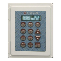
Oxigraf O2iM NEMA 4X Oxygen Analyzer
February 13, 2007 08-0427-B0, Manual, O2iM.doc Page 9
3. Getting Started
3.1 Analyzer Installation
3.1.1 Mounting the Analyzer
The O2iM enclosure is NEMA 4X rated for exposure to water and dust. Try to conform to the
following guidelines when selecting a location for mounting.
• Do not expose the analyzer to direct sunlight, which may increase the internal temperature
above the specification limit.
• Mechanical vibration can cause an increase in sensor noise. Mount the analyzer on
vibration isolators if significant vibration or shock is expected.
• Use waterproof conduit fittings installed in the holes provided at the bottom of the
enclosure.
• Extreme thermal transients can disrupt analyzer operation. Shield the enclosure from air
convection that may rapidly heat or cool the analyzer.
3.1.2 Power
The O2iM requires 24 VDC nominal (+20 to +32 VDC range) at 1.4 amps max, which may be
provided by the user or by the internal AC power supply. DC power is connected to the TB1
terminal strip on the terminal board. Note that the DC input power ground is also connected to the
sensor chassis ground. A 3-amp 2AG fuse (F2) on the controller board protects the sensor
electronics.
Caution: The sensor electronics may be damaged by reverse connection of
the DC power supply.
If the AC power supply is connected, provide a source of 100 to 230 VAC, 50 – 60 Hz power to the
power supply terminal strip. The power supply has an internal fuse but it is advisable to install an
inline 1-amp fuse in the AC line. The DC power supply output is connected to the power input
terminals at TB4.
3.1.3 RS-232 Interface
The O2iM can interface via a serial RS-232 data stream to the user's system. The default data format
is 9600 baud, 8 bit, no parity, with alternate baud rates of 2400, 4800, 19200, and 38400 selected by
interface commands. The signals present are Ground, RXD, (input) and TXD (output) at terminal
board TB2 pins 10, 11, and 12. Note that RS-232 UART is shared with the RS-485 Modbus
interface so only one interface may be active at a time. If the Modbus address is >= 240 then the
Modbus protocol will be enabled on the RS-232 interface.
Note: The RS-232 communications protocol and O2iM command set are covered in the
Remote Instrument Operation document.
3.1.4 RS-485 Interface
The RS-485 interface provides an alternate serial I/O channel to the O2iM via terminals at TB3 (RS-
485 +, RS-485 -, and Gnd). The default data format is 9600 baud, 8 bits, even parity for the Modbus
protocol. Installing a jumper block at JP2 enables RS-485 bus termination. Note that RS-232 UART
is shared with the RS-485 interface so only one interface may be active at a time. The Modbus
address must be between 1 and 239 to enable communication via the RS-485 interface.