Oxigraf O2iM NEMA 4X Oxygen Analyzer
February 13, 2007 08-0427-B0, Manual, O2iM.doc Page 22
5.23 Relay Allocation
The limit detector, warning, and system OK relays may be allocated to provide global status for all
channels or to indicate individual channel alarm / warning conditions. The global setting
(SysOK/Warn/A/B) activates the limit A and B relays when any channel triggers the A or B limit
detector. The WARNING and SYS OK relays are driven independent of the current channel status.
The channel relay mode (Channels 0-3) allocates each channel a relay, each of which is driven by the
limit detectors A and B qualified by the channel number. In this mode the alarm relay should be set
to respond to warning conditions.
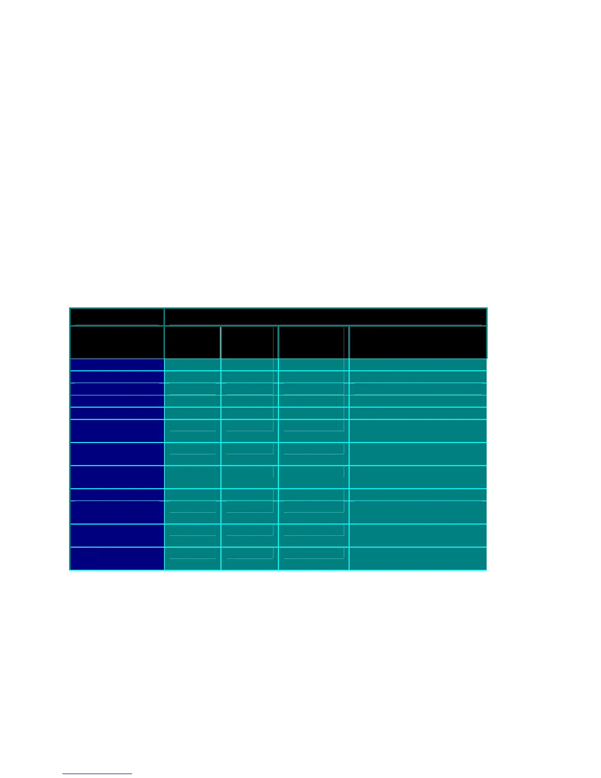
5.24 Horn/Strobe Mode
The Horn/Strobe mode determines the conditions for activation of the alarm relay, which is typically
connected to the audio alarm and strobe light. The activation condition is a function of the limit
alarms, (high/low O2) flow warning (flow, pressure, pump drive or low supply voltage) and system
fault as shown in the following table. Settings of 8-11 cause the alarm relay to activate at a 5 Hz rate
with a 3% duty cycle when a warning or fault condition is detected. The alarm relay is only activated
in Run mode and deactivated on any key press for the duration specified by the Alarm Acknowledge
Time parameter.
Activation Condition
Horn/ Strobe
Setting
Alarm
A
Alarm
B
Warning/
Fault
Alarm Relay State
0
Off
1
Steady Continuous on Alarm A
2
Steady Continuous on Alarm B
3
Steady Steady Continuous on Alarm A or B
4
Steady Continuous on Warning/Fault
5
Steady Steady Continuous on Alarm A or
Warning/Fault
6
Steady Steady Continuous on Alarm B or
Warning/Fault
7
Steady Steady Steady Continuous on Alarm A or B
or Warning/Fault
8
Flash Flash on Warning/Fault
9
Steady Flash Continuous on Alarm A,
Flash on Warning/Fault
10
Steady Flash Continuous on Alarm B,
Flash on Warning/Fault
11
Steady Steady Flash Continuous on Alarm A or B,
Flash on Warning/Fault
The priority for simultaneous situations is Alarm A, then Alarm B and finally Warning, from high to
low. Note that Alarm A and Alarm B are disabled when a fault condition exists, but not when a
warning is occurring.
5.25 Alarm Delay
The alarm delay time can be set in the range of 0 to 9999 seconds. An alarm condition must be true
for the alarm delay time in order to be recognized and generate an alarm.