Oxigraf O2iM NEMA 4X Oxygen Analyzer
February 13, 2007 08-0427-B0, Manual, O2iM.doc Page 6
2. Introduction
2.1 Product Description
This document describes the operation and user interface of the Oxigraf O2iM NEMA 4X oxygen
deficiency monitor. The O2iM integrates an Oxigraf oxygen sensor with auto calibration, vacuum
fluorescent alphanumeric display (VFD), keypad, limit detection relay, 4-20 mA analog output, horn
and strobe alarms, a serial communication link with Oxigraf protocol and an optional multipoint gas
sampling system.
The O2iM measures and displays the oxygen concentration in a gas sample drawn through the
instrument. Gas is pumped sequentially from up to four input sample ports, through the oxygen
sample cell, and out the exhaust port. An internal filter in the input line prevents contamination of
the sensor. A solenoid valve enables automatic single point calibration.
Autocal enables the O2iM to operate unattended for extended periods. With nothing to deteriorate,
wear out or degrade over time, the O2iM is virtually maintenance-free.
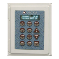
Measured oxygen concentration in percent volume fraction is displayed on a front panel
alphanumeric VFD display. Two lines of 16 characters show numeric data and the parameter units or
other information. The instrument mode is controlled via a front panel keypad array. Eight keys
select the mode (O2, Setup, Test, Cal 1, Cal 2, Flow, Alarms, and Help) while the other keys
facilitate selection and modification of parameters.
A warning horn and strobe is installed. The alarm may be programmed to activate on various
conditions of low O2, high O2, and analyzer fault conditions.
A terminal board provides the physical interface for DC power input, analog output, relays, and serial
link connections. The 100 to 230 VAC power is supplied by the user, or the user can connect the
terminal board directly to user-supplied DC power source. The terminal board also has connections
for the RS-232 and RS-485 links that provide for remote computer control and data acquisition. The
measured oxygen is displayed on the VFD display as well as driving a 4-20 mA output current
proportional to O2 concentration. The 4 mA and 20 mA O2 value endpoints are programmable from
the front panel.
A SPDT alarm relay is also activated in response to oxygen concentration
The Oxigraf sensor uses laser diode absorption technology to measure oxygen concentration in the
gas sample. A laser diode produces light in the visible spectrum at 760 nanometers, which is
absorbed by oxygen. To analyze oxygen the laser beam is focused through the sample gas onto a
detector. Oxygen concentration is inversely proportional to the amount of light reaching the detector.
An analysis is made every 10 ms., with the analyzer automatically zeroing at each measurement
interval by electronically tuning the laser to oxygen non-absorption wavelength. The peak
absorption measurement and line width measurement are used in an Oxigraf proprietary algorithm to
compute O2 concentration independent pressure or foreign gas composition.
Note: This analyzer is a CLASS 1 LASER PRODUCT. It contains an embedded laser
diode. The user cannot come into contact with the emission of laser radiation unless
the laser housing is disassembled. This requires special tools and is not part of any
user operation, maintenance or service procedure.