22
translation
6 OPERATION OF THE SPLITTING MECHANISM
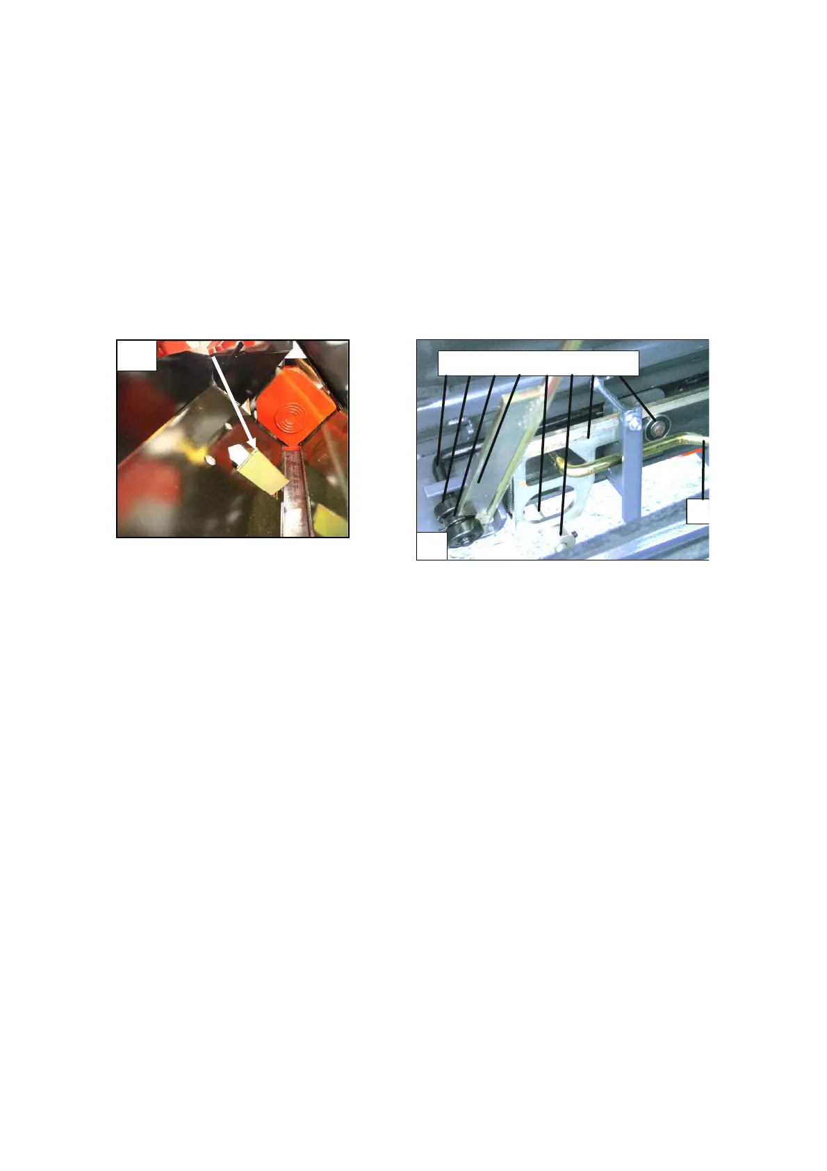
6.1 Solitting sensor, Fig. 19
The splitting sensor is placed in the splitting chute so that the falling log always hits
it straight on.
Small logs are also capable of starting the splitting motion.
Fig. 19. Splitting sensor
1 2 3 4 5 6 7 8
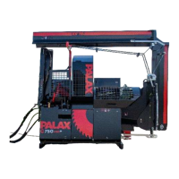
Fig. 20. Parts of the launching device
6.2 Parts of the launch device (Figure 20)
1. Lock bar
2 Support bearing
3 Guide bearing
4 Safety wedge
5 Sensor
6 Adjustment sleeve
7 Launch bar
8 Limiter bearing
9 Control lever for manual start
10 Stroke limiter
6.3 Operational principle of launching
1. As the wood falls into the splitting chute, it hits the tip of the sensor (Figure 18).
2. Sensor rod 5 (Figure 20) lifts up launch rod 7 by means of the adjustment
sleeve, which is released from behind fixed limiter bearing 8.
3. The launch rod 7 starts the splitting motion by means of the spring force.