29
translation
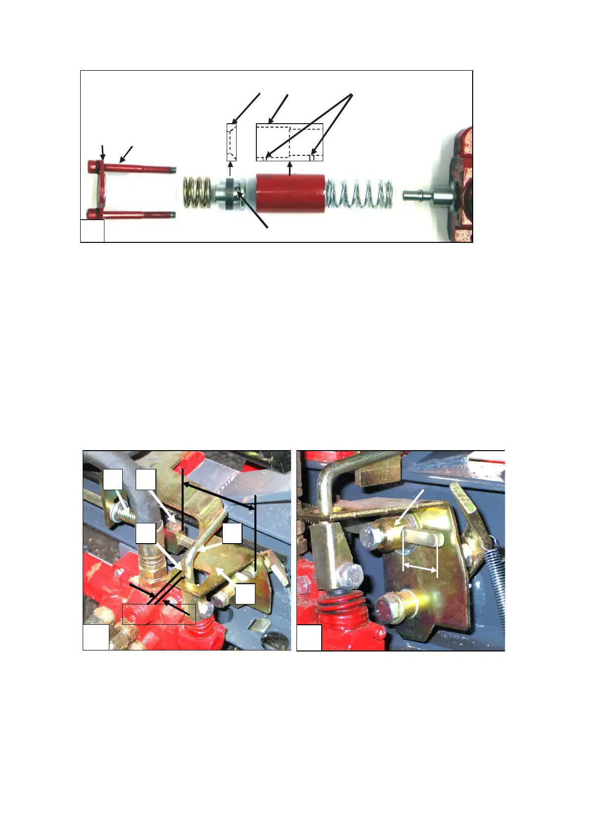
34
A
B
C
D
E
F
Fig. 34. Structure of the valve’s detent end
7.13 Initial settings of the valve (Figures 35 and 36)
The valve has been adjusted and test run at the factory.
The initial settings do not usually change so there is rarely any need for
readjustment.
In the long run, launch bar D makes a round groove about 2-3 mm deep in the
front edge of the square hole in control lever E.
In practice, this does not affect the operation of the machine in any way.
If launch spring B (Figure 35) is replaced, adjustment part C must be installed in its
original place.
The distance of the adjustment part from the end of the launch rod shall be about
105 mm.
35
A
D
E
B
C
Fig. 35. Basic settings of the valve 1/2
36
B
Fig. 36. Basic settings of the valve 2/2
NOTE! During adjustment of the hydraulic valve, the following must apply:
1. The splitting cylinder must be in the rear position.
2. The launch rod must be tightened.
3. The engine must be switched off