23
translation
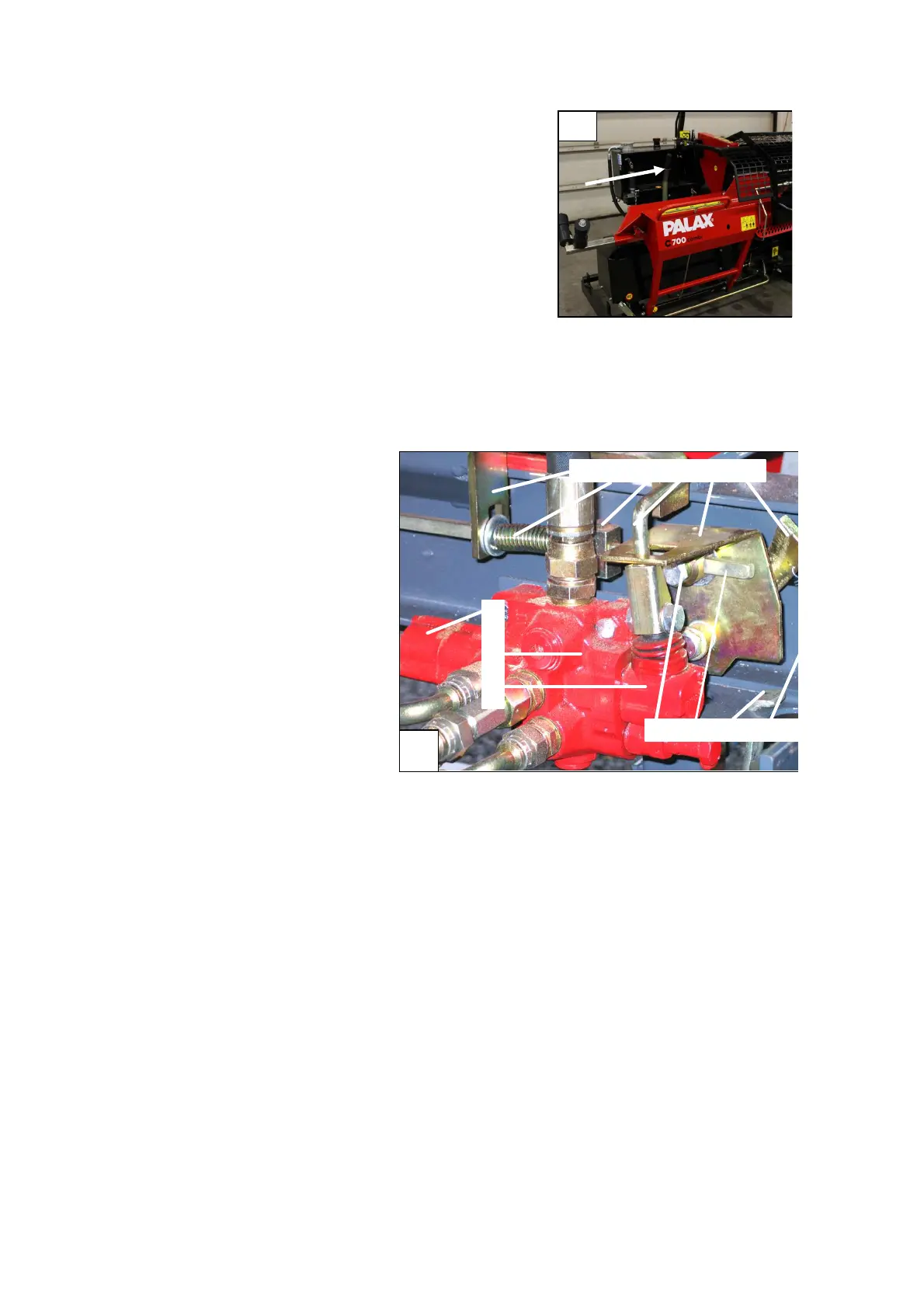
6.4 Hand-start of the splitting motion,
Figure 21
The splitting motion can also be started with
the hand-start lever by pushing the lever in
the direction of the arrow.
The manually operated launch lever affects
the control lever 9 for manual start (Fig. 20),
which depresses the bevel surface of the
launch rod 7. This makes the launch rod rise
from behind the limiter bearing 8, starting the
splitting operation.
Fig. 21. Manual starter for
the splitting operation
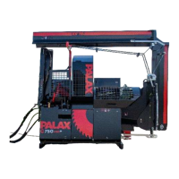
6.5 Parts of the
hydraulic valve
(Figure 22)
1 Tightener
2 Launch spring
3 Adjustment part of launch
spring
4 Launch bar
5 Control lever
6 Locking lever of net cage
7 Detent end of valve
8 Valve
9 Spool shifter
10 Shaft
11 Launch bar
12 Locking lever for pedal
Locking lever spring
7
8
9
Fig. 22. Parts of the hydraulic valve
6.6 Operation of the valve
Tightener, part 1
Stops and reverses the splitting cylinder, stops the valve in free-circulation and
tightens the launching spring 2 for a new movement.
Locking lever, part 6
Lifting up the protective net for the splitting chute shifts the locking rod 1 (Figure
20) by means of the safety wedge 4 into a position where the locking lever 6
(Figure 22) impedes the movement of the launch rod 4.