PTV 35/44/55/66 Installation Manual
Rev. 1.1 45
To prevent leaks during shipping and storage, hydraulic connections at liftgate are plugged. DO NOT
disconnect any plugs until ready to connect hoses to liftgate and hydraulic enclosure.
Steps:
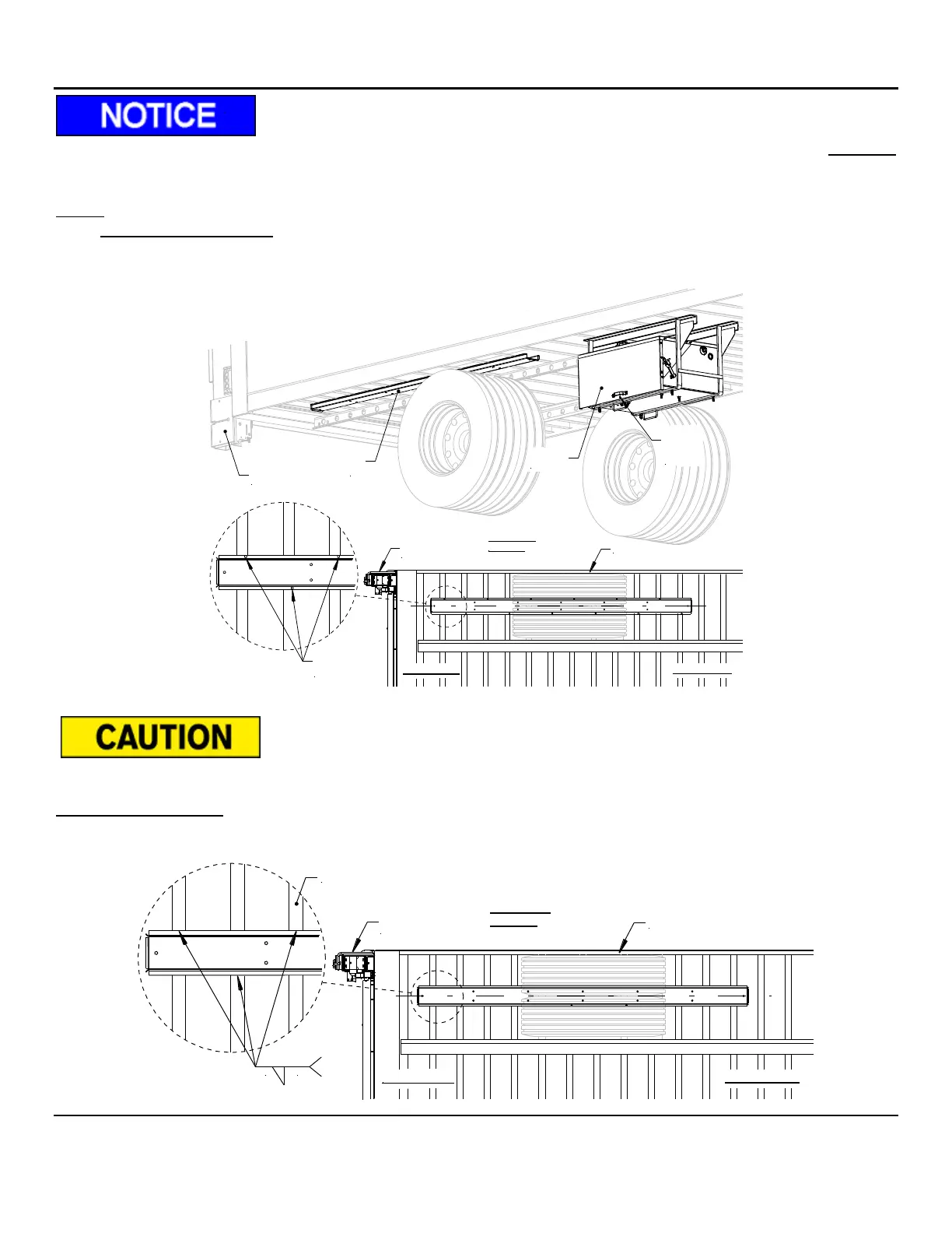
1. Hat Section (Bolt-On): Position the hat section on the right side of the vehicle centered between the
vehicle wheels. Clamp the hat section in place. Drill holes diagonally through the hat section flange and
the cross member. Secure with thread cutting flange screws.
DO NOT weld hat section with hydraulic hoses or electrical wires installed.
Hat Section (Welded): Position the hat section as described in the bolt on section. Secure the hat section to the
cross member by welding 1/8” x 1-1/4” welds every 12” minimum on both sides. Reference Fig.12 for welding
to crossmembers.