21
SINK
Input decision circuit
SOURCE
Input decision circuit
4.7kΩ
Terminal①
SINK current
Max. 8mA
0V
Terminal⑥
6WS1WS
Terminal⑦
0V-COM
0V
+5V
SINK
Input decision circuit
SOURCE
Input decision circuit
4.7kΩ
0V
+5V
SW1~6 COM Terminal
SINK current
Max. 8mA
Never use an external
pull-up resistor.
Terminal+V
SW□
SW1~6
Open-collector or volt-free contact
Internal Circuit of MK300 Inverter
█
Input Terminal for Multi-function Control Signal(Terminals No.
1
to
6
)
· General SINK/SOURCE input type. The external input devices, SINK input or
SOURCE input type, can be applicable. Please carry out the wiring as the wiring
example given below.
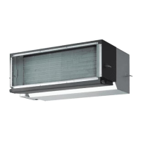
• Wiring Diagram and Precautions for SINK Input Setting
·Input open-collector signal or volt-free contact signal in between the input terminal ( ①
to ⑥ ) and the 0V-COM terminal ⑦ .
· Never supply ( + ) voltage from an external power source or use an external pull-up
resistor. Otherwise, it will cause malfunction.
· Note that the 0V-COM terminal ⑦ is internally connected with the terminal ( ⑩ ,
AN
)
and the internal circuit 0V. Moreover, never ground it.
· Each terminal has a max. SINK current of 8mA.
SINK
Input decision circuit
SOURCE
Input decision circuit
4.7kΩ
Terminal①
SOURCE current
Max. 8mA
0V
Terminal⑥
6WS1WS
Terminal⑦
0V-COM
0V
+5V
SINK
Input decision circuit
SOURCE
Input decision circuit
4.7kΩ
0V
+5V
SW1~6 COM Terminal
Never use an external
Pull-down resistor.
0V
SW□
SW1~6
Open-collector or volt-free contact
24V DC
SOURCE current
Max. 8mA
Internal Circuit of MK300 Inverter
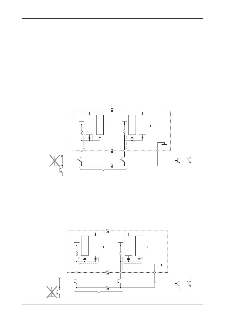
• Wiring Diagram and Precautions for SOURCE Input Setting
· Input open-collector signal or volt-free contact signal to the input terminal ( ① to ⑥ )
by supplying an external 24V power source. Connect the negative terminal (on the
0V side) of the external 24V power source to the 0V-COM terminal ⑦ .
· Never use an external Pull-down resistor. Otherwise, it will cause malfunction.
· Note that the 0V-COM terminal ⑦ is internally connected to the terminal ( ⑩ ,
AN
) and
the internal circuit 0V. Moreover, never ground it.
· Each terminal has a max. SOURCE current of 8mA.