22
█
Wiring for analog signal terminals (Terminal No.11 to 14)
· When parameter P004 is set to "1”, frequency setting will be made through external
potentiometer.
· When parameter P004 is set to "4" (4 to 20mA) or "5" (0 to 20mA), frequency setting
will be made through analog current signal.
· When the analog current signal is used, no resistor is required to be connected
between external terminals. (Resistor is built in.)
█
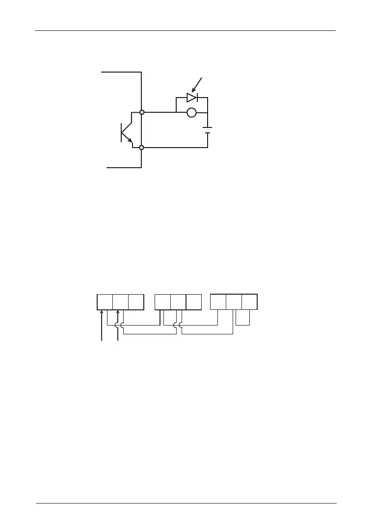
Wiring for RS485 communication terminals (Terminal No.16 to 18)
The following figure shows the terminals used when connection is made between PC
and PLC via RS485 communication lines.
⑯ ⑰ ⑱ ⑯ ⑰ ⑱
⑯ ⑰ ⑱
+
D+
D+
D-
D-
D-
E
Terminal station
Jumping out
· Use the shielded twisted-pair cable as communication cable, and separate it from
power lines or high-voltage circuits (20cm or more).
· The total wiring length of the communication cables must not exceed 500m.
· Jump out the terminal "D-" and "E" of inverter used as terminal station. Jumping is
not allowed for any other device.
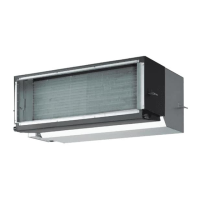
Internal circuit of
the inverter
Freewheel diode
Terminal ⑩
24V DC
+
×
Terminal
⑧,⑨
█
Wiring for Open-collector Output Terminals (Terminal No.8 to 10)
· When using open-collector output terminals to drive inductive loads, always connect
a freewheel diode.